DTC P0741: Damper Clutch System (Stuck off),
DTC P0742 Damper Clutch System (Stuck on)
DTC P0742 Damper Clutch System (Stuck on)
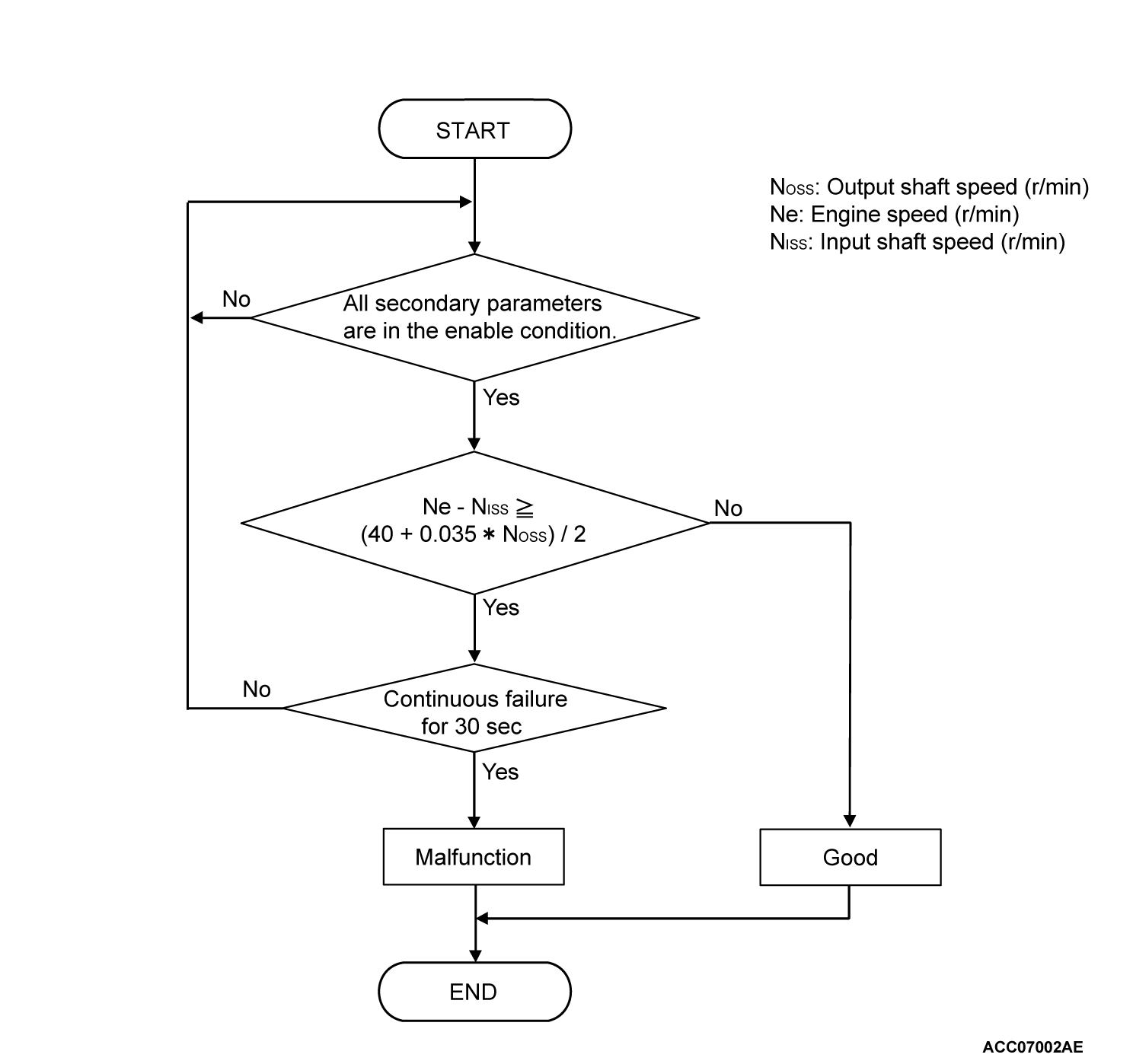
DESCRIPTIONS OF MONITOR METHODS <P0741>
When the input shaft speed sensor is normal, the engine speed signal is normal, and within the lock-up operation range, the slip speed of the torque converter exceeds the specified value.
MONITOR EXECUTION <P0741>
- Driving with the lock-up activated
MONITOR EXECUTION CONDITIONS (OTHER MONITOR AND SENSOR) <P0741>
Other Monitor (There is no temporary DTC stored in memory for the item monitored below)
- Not applicable
Sensor (The sensor below is determined to be normal)
- Not applicable
DTC SET CONDITIONS <P0741>
Check Conditions
- Lock-up status: engaging.
Judgment Criteria
- Engine speed - Input shaft speed: (40 + 0.035 × output shaft speed>)/2 or more. (30 seconds)
OBD-II DRIVE CYCLE PATTERN <P0741>
Driving at 55 km/h (34.2 mph) or more with the shift ranges of 3rd, 4th, 5th, and 6th gear. Maintain each shift range for 30 second or more.
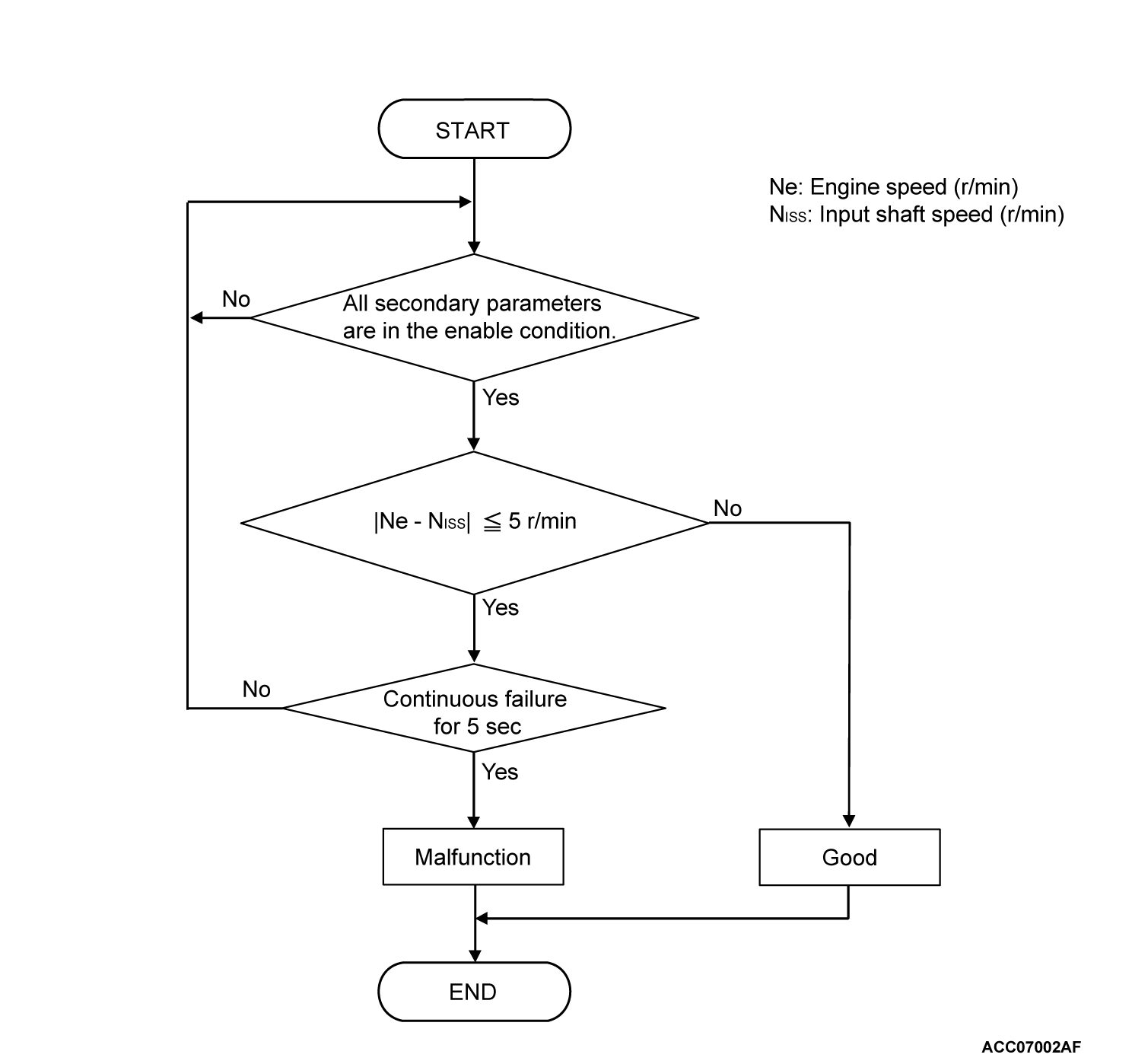
DESCRIPTIONS OF MONITOR METHODS <P0742>
When the input shaft speed sensor and the output shaft speed sensor are normal at the "D" range, the engine speed signal is normal, and within the non-lock-up operation range, the extremely low slip speed of the torque converter is detected continuously for a specified time.
MONITOR EXECUTION <P0742>
- Driving with the lock-up activated
MONITOR EXECUTION CONDITIONS (OTHER MONITOR AND SENSOR) <P0742>
Other Monitor (There is no temporary DTC stored in memory for the item monitored below)
- Not applicable
Sensor (The sensor below is determined to be normal)
- Not applicable
DTC SET CONDITIONS <P0742>
Check Conditions
- Output speed: more than 1,000 r/min.
- Lock-up status: Disengaging.
- Accelerator pedal position sensor opening: 3/8 or more
Judgment Criteria
- Calculated slip (Engine speed - Input shaft speed): 5 r/min or less. (5 seconds)
OBD-II DRIVE CYCLE PATTERN <P0742>
Driving at 55 km/h (34.2 mph) or less with the shift range of 3rd and 4th gear. Driving at 48 ± 2 km/h (29.8 ± 1.2 mph) with the 5th gear. Maintain each shift range for 1 second or more.
PROBABLE CAUSES
- When the DTC P0712, P0713: transmission fluid temperature sensor system is stored
- Malfunction of the P2763, P2764: Lock-up and Low-reverse brake linear solenoid valve system
- Poor installation of the engine and A/T (deviation to the axial direction)
- Malfunction of the torque converter
- Malfunction of the valve body assembly
DIAGNOSIS
STEP 1. Hydraulic pressure test
STEP 2. Check the lock-up and low-reverse brake linear solenoid.
Check for P2763 (lock-up and low-reverse brake linear solenoid open) and P2764 (lock-up and low-reverse brake linear solenoid short). Refer to  .
. Repair or replace the failure section.
 .
.Is the check result normal?
 Repair or replace the failure section.
STEP 3. Check the transmission fluid temperature sensor, input shaft speed sensor, and output shaft speed sensor.
Check the following DTCs: P0712 (Transmission fluid temperature sensor (short circuit)), P0713 (Transmission fluid temperature sensor (open circuit)), P0715 (Input shaft speed sensor) and P0720 (output shaft speed sensor).  Repair or replace the failure section.
Is the check result normal?
 Repair or replace the failure section.
STEP 4. Check the malfunction of CAN communication system.
Are the DTC for CAN communication system malfunction (U0001, U0100, U0141, P1705, P1706) stored?
 Repair or replace the failure section.
STEP 5. Check the TCM connector pin terminal and the connection status.
Is the check result normal?
 Repair or replace the failure section.
STEP 6. Erase the DTC, and drive the vehicle for a while.
Check that the normal code is displayed. The procedure is complete.
Is the check result normal?
 The procedure is complete.
STEP 7. Check the installation position of the engine and A/T.
Is the check result normal?
 Replace the transaxle assembly.
 Repair or replace the failure section.
![[Previous]](../../../buttons/fprev.png)
![[Next]](../../../buttons/fnext.png)

