DTC P0713: Transmission Fluid Temperature Sensor System (Open Circuit)
DESCRIPTIONS OF MONITOR METHODS
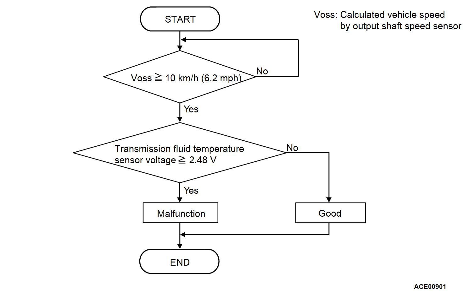
With the vehicle speed 10 km/h (6.2 mph) or more, when the status of transmission fluid temperature -40°C (-40°F) or less is detected
MONITOR EXECUTION
- Vehicle speed: more than 10 km/h (6.2 mph)
MONITOR EXECUTION CONDITIONS (OTHER MONITOR AND SENSOR)
Other Monitor (There is no temporary DTC set in memory for the item monitored below)
- P0846: 2-6 brake pressure switch system
- P0876: High clutch pressure switch system
- P0988: Low-reverse brake pressure switch system
Sensor (The sensor below is determined to be normal)
- Not applicable
DTC SET CONDITIONS
Check Conditions
- Vehicle speed: 10 km/h (6.2 mph) or more.
Judgment Criteria
- Transmission fluid temperature sensor voltage: 2.48 V or more [-40°C (-104°F) or less]. (At once)
OBD-II DRIVE CYCLE PATTERN
Drive with the vehicle speed 10 km/h (6.2 mph) or more.
PROBABLE CAUSES
- Malfunction of the transmission fluid temperature sensor system (open circuit) circuit
- Damaged harness or connector
- Malfunction of the transmission fluid temperature sensor system (open circuit)
- Malfunction of the TCM
DIAGNOSIS
STEP 1. Check the TCM terminal voltage.
[TCM connector (harness side, connected)]
Turn ON the ignition switch, and check the voltage between O/TS terminal and O/T- terminal.
- Transmission fluid 20°C (68°F): Approx. 2.52 V
- Transmission fluid 80°C (176°F): Approx. 0.69 V
Is the check result normal?
STEP 2. Check the transmission fluid temperature sensor as a single unit.
STEP 3. Check for continuity in O/TS, O/T- line between the A/T control solenoid valve assembly connector and TCM connector.
When the continuity check result is OK, check that the wiring harness is not shorted to the body and other wiring harness. Repair the connector(s) or wiring harness.
Is the check result normal?
 Repair the connector(s) or wiring harness.
STEP 4. Check for open circuit and short to ground in VIG1, VIG2 line between the fusible link and the TCM connector, and check for open circuit in GND1, GND2 line between the TCM connector and body ground.
STEP 5. Check the TCM connector pin terminal and the connection status.
Is there a failure point?
 Repair or replace the failure section.
 Replace the TCM.
![[Previous]](../../../buttons/fprev.png)
![[Next]](../../../buttons/fnext.png)

