VARIABLE VALVE LIFT MECHANISM CHECK
Required Special Tools:
- MB992744: Vehicle communication interface-Lite (V.C.I.-Lite)
- MB992745: V.C.I.-Lite main harness A
- MB992747: V.C.I.-Lite USB cable short
- MB992748: V.C.I.-Lite USB cable long
- MB991958: Scan Tool (M.U.T.-III Sub Assembly)
- MB991824: Vehicles Communication Interface (V.C.I.)
- MB991827: M.U.T.-III USB Cable
- MB991910: M.U.T.-III Main Harness A (Vehicles with CAN communication system)
| note | If the diagnostic trouble code related to the valve lift is set and the valve lift mechanism is questioned about its poor operation, perform this check. |
1. Turn the ignition switch to the "LOCK" (OFF) position.
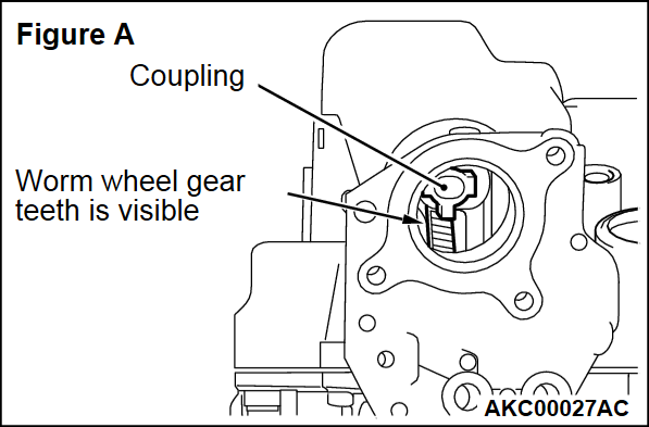
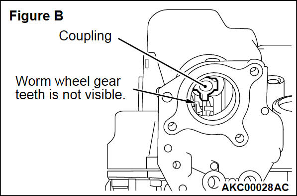
3. Visually check the position of the worm wheel through the variable valve lift control motor mounting hole. If the gear teeth is visible as shown in figure A, go to Step 4. If the gear teeth is not visible as shown in figure B, go to Step 5.
4.
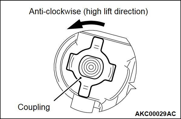
Insert a 12-point socket (24 mm) with a mini torque wrench into the coupling. Check rotational torque by turning the coupling counterclockwise.
| caution |
|
- If the rotational torque is 0.7 N·m (6 in-lb) or less, go to Step 5.
- If the rotational torque is more than 0.7 N·m (6 in-lb) and 3 N·m (27 in-lb) or less, turn the coupling counterclockwise once while keeping the torque 3 N·m (27 in-lb) or less. After completion of the repair, perform road test to check whether the malfunction occurs again.
- If the rotational torque exceeds 3 N·m (27 in-lb), replace the rocker arm and camshaft assembly. (Refer to
 ).
).
6. Visually check the rocker arm and camshaft assembly for missing, breakage, falling off, jammed foreign matters, etc.
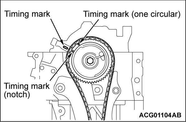
7. Rotate the crankshaft clockwise. Align the timing mark of the rocker shaft holder with the timing mark (notch) of the V.V.T. sprocket. Therefore, the No. 1 cylinder is set at the top dead center on its compression stroke.
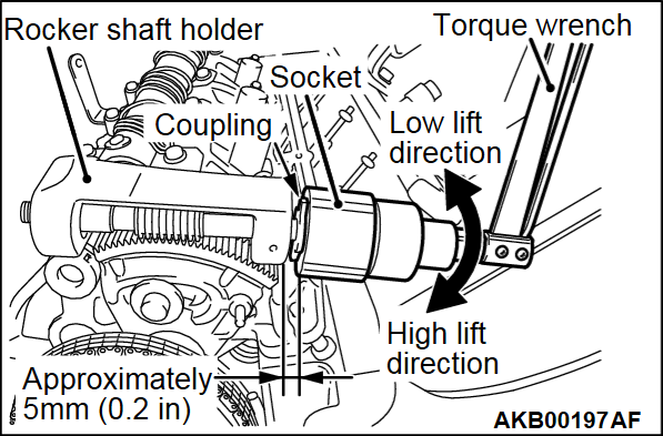
8. Insert a 12-point socket (24 mm) into the position on the coupling approximately 5 mm (0.2 inch) away from the rocker shaft holder. Connect the mini torque wrench.
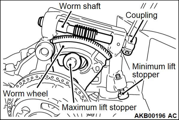
9. Perform the visual check of the worm wheel. If the jam occurs at the position where the worm wheel pushes the minimum lift stopper or the maximum lift stopper, rotate the mini torque wrench to the following direction releasing the jam. Check the rotational torque and perform the conformity determination as follows:
ROTATING DIRECTION
- If the worm wheel is placed in the position where the worm wheel pushes the minimum lift stopper, rotate the mini torque wrench counterclockwise.
- If the worm wheel is placed in the position where the worm wheel pushes the maximum lift stopper, rotate the mini torque wrench clockwise.
CONFORMITY DETERMINATION
- If the jam can be released with the rotational torque less than 3 N·m (27 in-lb), repeat the jam by the trial run after the repair. If the jam reoccurs, replace the rocker arm and camshaft assembly. (Refer to
 ).
). - If the rotational torque is more than 3 N·m (27 in-lb), replace the rocker arm and camshaft assembly. (Refer to
 ).
).
10. If the jam does not occur at the position where the worm wheel pushes the minimum lift stopper or the maximum lift stopper, check as follows:Slowly rotate the mini torque wrench. Move the worm wheel from the minimum lift position to the maximum lift position.
Check the rotational torque and perform the conformity determination as follows:
CONFORMITY DETERMINATION
- If the rotational torque is more than 2 N·m (18 in-lb), replace the rocker arm and camshaft assembly. (Refer to
 ).
). - If the rotational torque is more than 0.7 N·m (6 in-lb) and less than 2 N·m (18 in-lb), repeat the jam by the trial run after the repair. If the jam reoccurs, replace the rocker arm and camshaft assembly. (Refer to
 ).
). - If the rotational torque is less than 0.7 (6 in-lb) N·m, the rocker arm and camshaft assembly is not defective.
11. To prevent the gear jam, let the worm wheel push the minimum lift stopper. Rotate the coupling two revolutions counterclockwise.
14.
| caution | To prevent damage to scan tool (M.U.T.-III), always turn the ignition switch to the "LOCK" (OFF) position before connecting or disconnecting scan tool (M.U.T.-III). |
![[Previous]](../../../buttons/fprev.png)
![[Next]](../../../buttons/fnext.png)
