[Previous][Next]
REMOVAL AND INSTALLATION
 
 
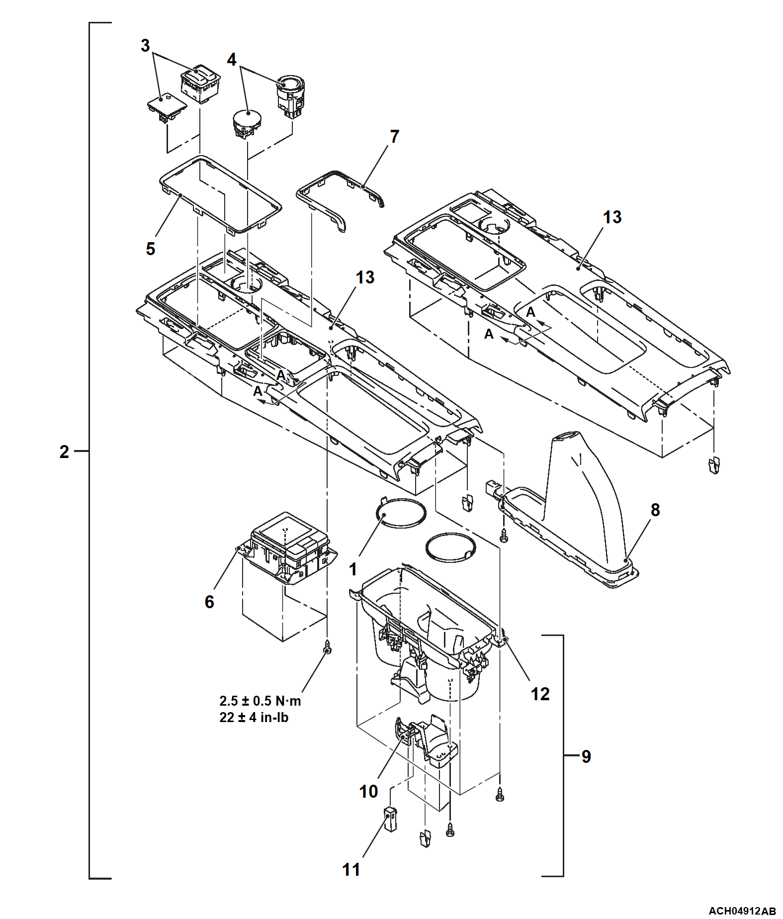
<Lever type parking brake>
Pre-removal and Post-installation Operation
  • Selector Lever Knob Removal and Installation (Refer to GROUP 23A - Transmission Control ).
  • Instrument Panel Garnish Removal and Installation (Refer to ).
  • Instrument Panel Mat Clip Removal and Installation (Refer to ).
  • Floor Console Assembly Rear Removal and Installation (Refer to ).
Removal steps
1.Floor console box mat
2.Shift lever panel assembly
>>A<<3.Heated seat switch (front) or switch plug
4.Drive mode selector or switch plug
Shift indicator panel assembly (Refer to GROUP 23A - Transmission Control ).
5.Instrument panel garnish center
6.Touchpad controller
7.Instrument panel garnish center <Vehicles with touchpad controller>
8.Parking brake lever cover
9.Floor console box cup holder assembly
10.Spotlight cover
11.Spotlight
12.Floor console box cup holder
13.Shift lever panel
 
 
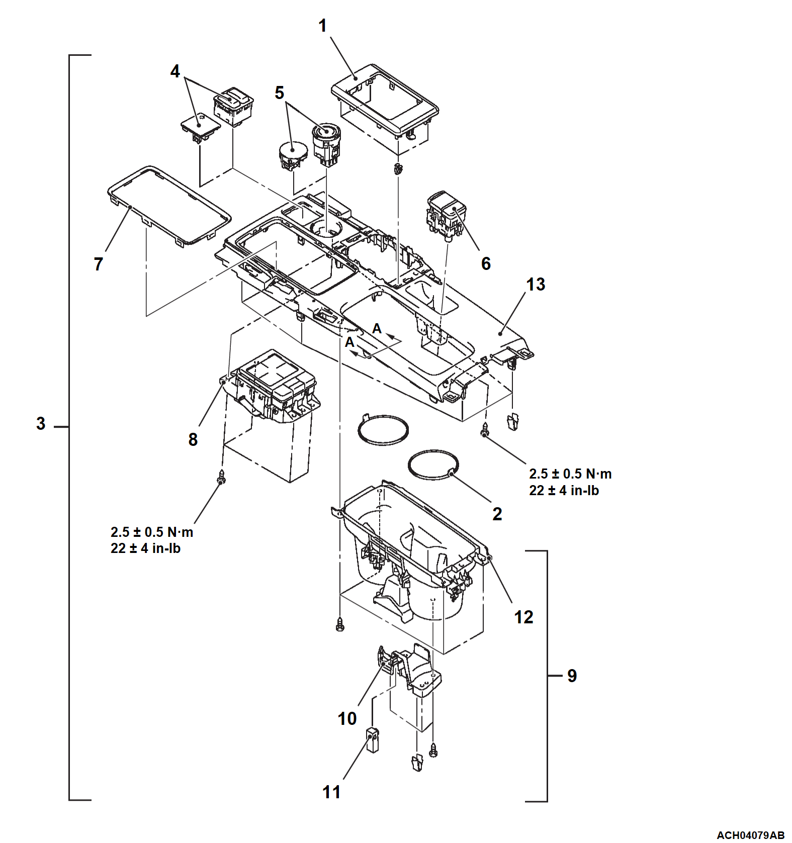
<Electric parking brake>
Pre-removal and Post-installation Operation
  • Selector Lever Knob Removal and Installation (Refer to GROUP 23A - Transmission Control ).
  • Instrument Panel Mat Clip Removal and Installation (Refer to ).
  • Floor Console Assembly Rear Removal and Installation (Refer to ).
Removal steps
<<A>>1.Instrument panel garnish center <Vehicles with touchpad controller>
2.Floor console box mat
Instrument panel garnish (Refer to ).
3.Shift lever panel assembly
>>A<<4.Heated seat switch (front) or switch plug
5.Drive mode selector or switch plug
6.Electric parking brake switch
Shift indicator panel assembly (Refer to GROUP 23A - Transmission Control ).
7.Instrument panel garnish center
8.Touchpad controller
9.Floor console box cup holder assembly
10.Spotlight cover
11.Spotlight
12.Floor console box cup holder
13.Shift lever panel
 
 
REMOVAL SERVICE POINT
 
 
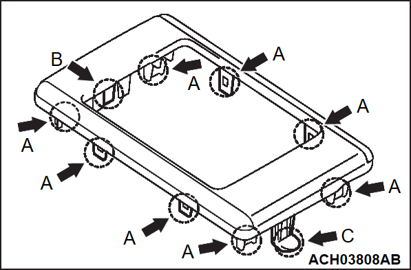
<<A>> INSTRUMENT PANEL GARNISH CENTER REMOVAL
Remove the engagement between each claw on the instrument panel garnish center and the shift lever panel according to the steps below.
1. Lift the instrument panel garnish center slightly and remove the engagement between claws A on the right and left side of the vehicle and the shift lever panel.
2. Remove the engagement between claw B on the front side of the vehicle and the shift lever panel.
3. Remove the engagement between claw C on the rear side of the vehicle and the shift lever panel.


INSTALLATION SERVICE POINT
 
 
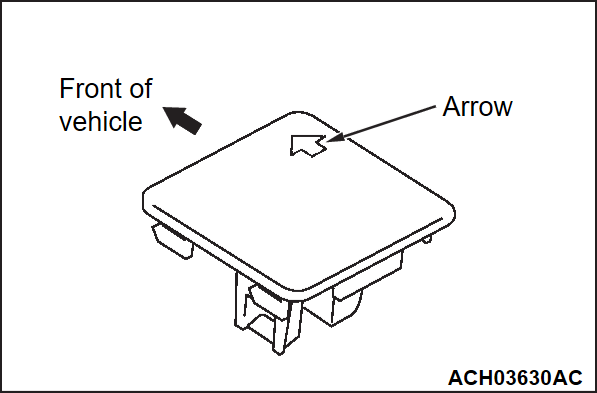
>>A<< SWITCH PLUG INSTALLATION
Install the switch plug in the direction shown in the figure.