On Board Diagnosis Function
ON BOARD DIAGNOSIS ITEM
The following meter functions can be checked during combination meter self-diagnosis mode:
- Pointer sweep of speedometer, tachometer and gauges.
- Illumination of color patterns for meter displays.
- Illumination of all lamps/LEDs that are controlled by the combination meter (regardless of switch status).
- Error code
METHOD OF STARTING
How to Initiate Self-Diagnosis Mode
- Turn the electric motor switch OFF.
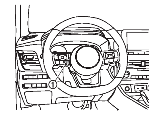
- While pressing the control switch
 , turn the electric motor switch ON.
 - Keep pressing the control switch for 1 seconds or more.
- Press the control switch at least 3 times. (Within 7 seconds after the electric motor switch is changed to ON.)
- “Work instruction code” is indicated in the top portion of information display and self-diagnosis is started.
note When on-board diagnosis does not start, check the following items and replace combination meter if the check results are normal. - Combination meter power supply and ground circuits. Refer to Diagnosis Procedure
 .
. - Steering switch signal circuits. Refer to Component Function Check
 .
.
- Combination meter power supply and ground circuits. Refer to Diagnosis Procedure
- The mode switches in the order shown below each time the control switch is pressed.
note - If the control switch is not operated for 20 seconds or more, the self-diagnosis mode is automatically cancelled.
- The self-diagnosis mode is cancelled by turning the key switch OFF.
- The self-diagnosis mode is cancelled by engine speed 170 rpm or more.
| Test order | Test item | Description | |||
| 1 | Work instruction code | This item is displayed, but not used. | |||
| 2 | Spare parts No. | ||||
| Soft ware code | |||||
| Flash rom No. | |||||
| 3 | EEPROM code | ||||
| 4 | Hardware code | ||||
| 5 | PCB code | ||||
| 6 | Circuit check | The pointer of the following items moves from 0 to MAX then from MAX to 0.
| |||
| 7 – 10 | Color check | Performs the color check of the information display. | |||
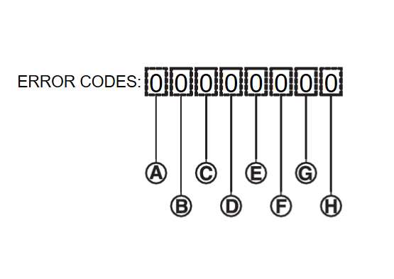
| 11 | Error code* | Displays the error code of the following items.
| |||
| 12 | Warning/indicator light check | All warning/indicator light illuminate. | |||
| note | When the control switch is pressed during the indication of "Test order 12", test item returns to "Test order 2". |
*: Error Code
| Item | Code | Description | Action to take/Reference | |
 | Speedometer | 0 | Normal | — |
| 1 | A vehicle speed signal can not be received from ECM. | Perform "Diagnostic Trouble Code" of “ENGINE”. Refer to DIAGNOSTIC TROUBLE CODE CHART  . . | ||
| 2 | A vehicle speed signal received from ECM is abnormal. (FFFFh) | |||
 | Power gauge | 0 | Normal | — |
| 1 | Total Drive Power Display CAN signal can not be received from PHEV-ECU | Perform "Diagnostic Trouble Code" of “PHEV-ECU”. Refer to DIAGNOSTIC TROUBLE CODE CHART  . . | ||
| 2 | Abnormal input | |||
 | Fuel gauge | 0 | Normal | — |
| 1 | Fuel gauge circuit is short. | Refer to Component Function Check . . | ||
| 2 | Fuel gauge circuit is open. | |||
 | Engine coolant temperature gauge | 0 | Normal | — |
| 1 | HV Battery Energy Level CAN signal can not be received from PHEV-ECU. | Perform "Diagnostic Trouble Code" of “PHEV-ECU”. Refer to DIAGNOSTIC TROUBLE CODE CHART  . . | ||
| 2 | Abnormal input | |||
 |
| 0 | Normal | — |
| 1 | When judging that the illumination control switch signal circuit is short-circuited for 5 minutes or more. | Refer to Component Function Check . . | ||
| 2 | When judging that the steering switch (control switch) signal circuit is short-circuited for 5 minutes or more. | Refer to Component Function Check . . | ||
| 3 | When judging that the illumination control switch and steering switch (control switch) signal circuit are short-circuited for 5 minutes or more. | Refer to Component Function Check and Component Function Check and Component Function Check . . | ||
 | — | 0 | Displays “0” constantly. | — |
 | — | 0 | Displays “0” constantly. | — |
 | — | 0 | Displays “0” constantly. | — |
![[Previous]](../../../buttons/fprev.png)
![[Next]](../../../buttons/fnext.png)

