FUEL INJECTOR CHECK
CHECK THE OPERATION SOUND
1. Set the vehicle to the continuous idling mode (Refer to CONTINUOUS IDLING MODE )
)
 )
)| caution | Beware that, even if the injector to be checked is not operating, the operation sound of other injectors may be heard. |
2. Use a stethoscope to listen to the operation sound (ticks) from the injectors.
3. Verify that the operation sound increases with the higher engine speed.
| note | If the operating sound cannot be heard, inspect the injector actuation circuit. |
MEASUREMENT OF RESISTANCE BETWEEN TERMINALS
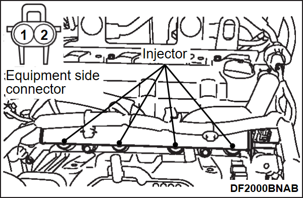
1. Disconnect the injector connector.
2. Measure the resistance between terminals.
Standard value: 10.5 – 13.5 Ω [at 20°C (68°F)]
3. If the resistance is deviates from the standard value, replace the injector (Refer to FUEL INJECTOR REMOVAL AND INSTALLATION )
)
 )
)CHECK THE INJECTION CONDITION
1. Release the residual pressure in the fuel pipe line to prevent the fuel from running out (Refer to FUEL PUMP CONNECTOR DISCONNECTION (HOW TO REDUCE PRESSURIZED FUEL PRESSURE) ).
).
 ).
).| caution | Cover the hose connection with rags to prevent splash of fuel that could be caused by some residual pressure in the fuel pipe line. |
2. Remove the fuel high-pressure hose at the fuel rail (Refer to FUEL INJECTOR REMOVAL AND INSTALLATION ).
).
 ).
).3. Remove the injector (Refer to FUEL INJECTOR REMOVAL AND INSTALLATION ).
).
 ).
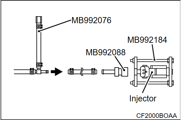
).4. Assemble the special tool called injector test set (MB992076) as shown in the figure according to the following procedure.
(1) Disconnect the injector mounting hose.
(2) Remove the adapter for mounting injector and attach the special tool Injector test nipple (MB992088) instead.
(3) After attaching the injector on the special tool Injector test nipple (MB992088), secure it with the special tool injector holder (MB992184).
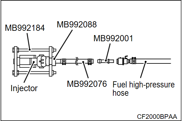
5. Mount the injector test set (MB992076) prepared with the special tool hose adapter (MB992001) onto the fuel high-pressure hose.
6. Connect the scan tool (M.U.T.-III SE) to the data link connector.
7. Operate the electric motor switch without depressing the brake pedal and turn the power supply mode of electric motor switch to ON.
8. Select "Item No. 20" of the scan tool (M.U.T.-III SE) actuator test to drive the fuel pump.
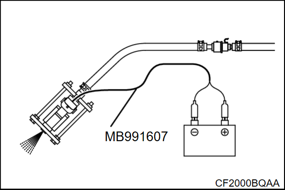
9. Connect the special tool Injector test harness (MB991607) between the injector and auxiliary battery to drive the injector.
10. Check each injector for spray conditions. The condition can be considered satisfactory unless it is extremely poor.
11. Stop the actuation of the injector, and check for leakage from the injector nozzle.
Standard value: 1 drop or less per minute
12. After Turning off the power supply mode of the electric motor switch, remove the scan tool (M.U.T.-III SE).
13. Actuate the injector until it does not spray fuel any longer, then drain the fuel inside the special tool.
14. Remove the special tool.
15. When the spray condition is extremely poor or any fuel leaks from the injector nozzle, replace the injector.
16. Replace the injector and fuel high-pressure hose in the original places (Refer to FUEL INJECTOR REMOVAL AND INSTALLATION ).
).
 ).
).![[Previous]](../../../buttons/fprev.png)
![[Next]](../../../buttons/fnext.png)


