Removal and Installation
REMOVAL
1. Remove the timing chain. Refer to Removal and Installation.Removal and Installation

2. Disconnect the harness connectors from the intake camshaft position sensor, exhaust camshaft position sensor, engine coolant temperature sensor, EVAP canister purge volume control solenoid valve, high pressure fuel pump and air fuel ratio (A/F) sensor 1.
3. Remove camshaft position sensors.
| caution | Do not reuse O-rings. |
4. Release harness retainers and reposition harness.
5. Remove the high pressure fuel pump insulator. Refer to Removal and Installation .
.
 .
. 6. Remove the high pressure fuel tube, high pressure fuel pump and high pressure fuel pump lifter. Refer to Removal and Installation .
.
 .
.7. Remove electric intake valve timing control actuator target from camshaft sprocket (INT).
| caution | Do not reuse electric intake valve timing control actuator target. |
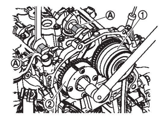
8. Remove the camshaft sprocket [INT]  and camshaft sprocket [EXH]
  using the following procedure:
 and camshaft sprocket [EXH]
  using the following procedure:
| caution | Do not rotate the crankshaft or camshafts while the timing chain is removed. It can cause damage to the valves and pistons. |
(1) Secure hexagonal part  of the camshaft with a suitable tool and loosen the camshaft sprocket bolt.
 of the camshaft with a suitable tool and loosen the camshaft sprocket bolt.
 (2) Remove the camshaft sprocket bolt and camshaft sprockets for both camshafts.
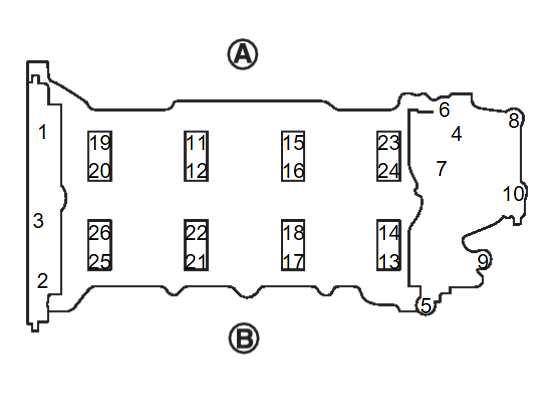
9. Loosen camshaft bracket bolts in reverse of the sequence shown.
| note | Camshaft bracket (No.1) and camshaft position sensor bracket use liquid gasket and can be difficult to remove. Do not damage mating surface when removing. |
 | : Exhaust side |
 | : Intake side |
10. Remove camshaft signal plate (INT) and camshaft signal plate (EXH) (if necessary).
11. Remove the valve lifters.
| note | Check installation positions, and set them aside in the order removed. |
INSTALLATION
If replacing intake camshaft position sensor or exhaust camshaft position sensor, perform "Electric intake valve timing control actuator position learning". Refer to Work Procedure .
.
 .
.1. Install the valve lifter.
- Install them in the same position from which they were removed.
2. If removed, install the camshaft signal plate (INT) and camshaft signal plate (EXH).
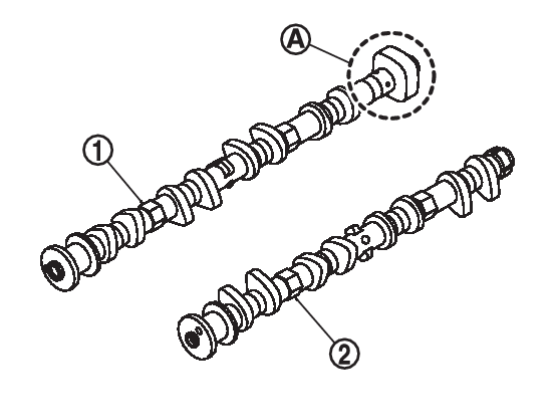
3. Install the camshaft [INT]  and camshaft [EXH]
  .
.
 and camshaft [EXH]
  .
.| note | The distinction between the intake and exhaust camshaft can be made by the shape of the rear  of the exhaust camshaft. of the exhaust camshaft. |
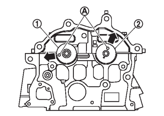
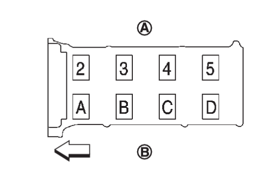
4. Install camshaft brackets.
- Install by referring to identification mark on upper surface mark.
- Install so that identification mark can be correctly read when viewed from the exhaust side.

: Exhaust side 
: Intake side 
: Engine front
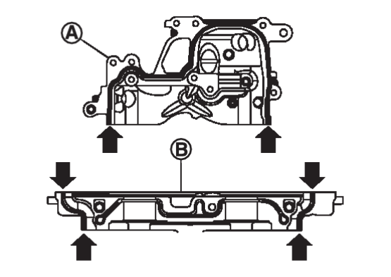
- Install camshaft bracket (No. 1) and camshaft position sensor bracket.
- Apply a bead of liquid gasket [3.4 - 4.4 mm (0.134-0.173 in)] to camshaft bracket [No. 1]
 and camshaft position sensor bracket
  as shown.Use Genuine RTV Silicone Sealant or an equivalent. Refer toRecommended Chemical Products and SealantsRecommended Chemical Products and Sealants
 .
.caution - The components must be installed within 5 minutes of the liquid gasket application.
- Do not re-tighten bolts after the 5 minutes have elapsed.
- Allow 30 minutes for the liquid gasket to set before adding oil to the engine.
note Remove liquid gasket that protrudes at locations (  ) shown.
- Apply a bead of liquid gasket [3.4 - 4.4 mm (0.134-0.173 in)] to camshaft bracket [No. 1]
5. Tighten camshaft bracket bolts in five steps in the order as shown.
| Step 1 (bolts 1 - 26) | : 1.96 N·m (0.20 kg-m, 17 in-lb) |
| Step 2 (bolts 11 - 26) | : 5.88 N·m (0.60 kg-m, 52 in-lb) |
| Step 3 (bolts 1 - 10) | : 5.88 N·m (0.60 kg-m, 52 in-lb) |
| Step 4 (bolts 11 - 26) | : 10.41 N·m (1.1 kg-m, 8 ft-lb) |
| Step 5 (bolts 1 - 10) | : 10.41 N·m (1.1 kg-m, 8 ft-lb) |
 | : Exhaust side |
 | : Intake side |
| caution | After tightening camshaft bracket bolts, be sure to wipe off excessive liquid gasket from the parts listed below.
|
6. Install the camshaft sprocket [INT]  and camshaft sprocket [EXH]
  .
.
 and camshaft sprocket [EXH]
  .
.- Secure hexagonal part
 of the camshaft with a suitable tool and tighten the camshaft sprocket bolts to the specified torque.
Camshaft sprocket (INT) bolt Step 1 : 35.0 N·m (3.6 kg-m, 26 ft-lb) Step 2 : 28° - 33° Camshaft sprocket (EXH) bolt Step 1 : 50.0 N·m (5.1 kg-m, 37 ft-lb) Step 2 : 45° - 50°
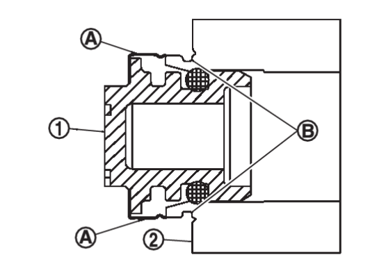
7. Install the electric valve timing control actuator target  into the camshaft sprocket (INT)
  until the metal ring
  clips into the groove
  in the sprocket.
 into the camshaft sprocket (INT)
  until the metal ring
  clips into the groove
  in the sprocket.
| caution | Do not reuse electric valve timing control actuator target. |
| note | Apply new engine oil to the electric valve timing control actuator target O-ring if necessary. Make sure that no engine oil adheres to front face of camshaft sprocket (INT). |
8. Install the timing chain. Refer to Removal and Installation.Removal and Installation

9. Install the high pressure fuel pump. Refer to Removal and Installation.Removal and Installation

10. Install the high pressure fuel tube. Refer to Removal and Installation.Removal and Installation

11. Check and adjust valve clearances. Refer to Inspection and Adjustment.Inspection and Adjustment

12. Installation of the remaining components is in the reverse order of removal.
![[Previous]](../../../buttons/fprev.png)
![[Next]](../../../buttons/fnext.png)
