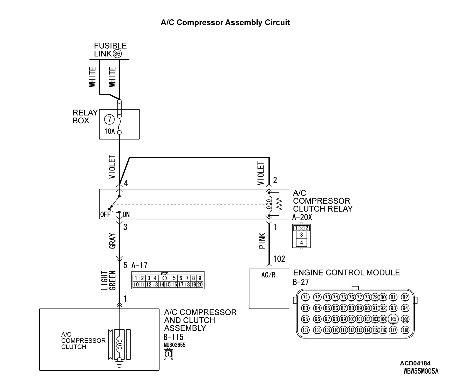
INSPECTION PROCEDURE 3: The Compressor does not Work.
FUNCTION
Compressor that recovers the refrigerant, which evaporated in the evaporator and became a high-temperature and high-pressure gas, and turns it into liquid again.
PROBABLE CAUSES
- Malfunction of connector.
- Malfunction of the harness (A/C compressor circuit is open/shorted to ground)
- Malfunction of the A/C compressor.
- Malfunction of the A/C compressor clutch relay.
- Malfunction of the engine control module.
DIAGNOSIS
Required Special Tool:
- MB991223: Harness Set
- MB992006: Extra Fine Probe
STEP 1. Using scan tool MB991958, diagnose the CAN bus line.
(1)
| caution | To prevent damage to scan tool MB991958, always turn the ignition switch to the "LOCK" (OFF) position before connecting or disconnecting scan tool MB991958. |
(2) Turn the ignition switch to the "ON" position.
(3) Diagnose the CAN bus line.
(4) Turn the ignition switch to the "LOCK" (OFF) position.
Is the CAN bus line found to be normal?
STEP 2. Using scan tool MB991958, read the diagnostic trouble code.
Check if an A/C control panel DTC is set.
(1) Connect scan tool MB991958 to the data link connector.
(2) Turn the ignition switch to the "ON" position.
(3) Check if the DTC is set.
(4) Turn the ignition switch to the "LOCK" (OFF) position.
Is the DTC set?
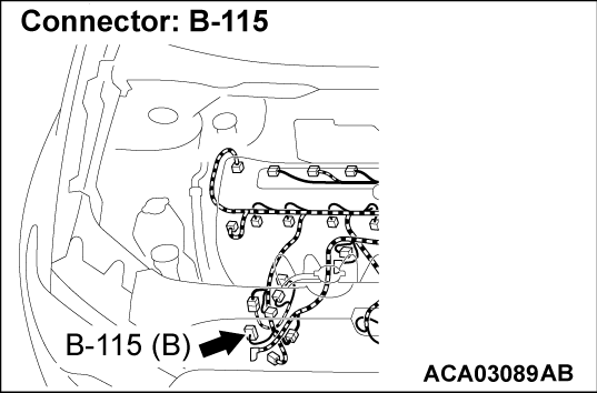
STEP 3. Check A/C compressor and clutch assembly connector B-115 for loose, corroded or damaged terminals, or terminals pushed back in the connector.
Is A/C compressor and clutch assembly connector B-115 in good condition?
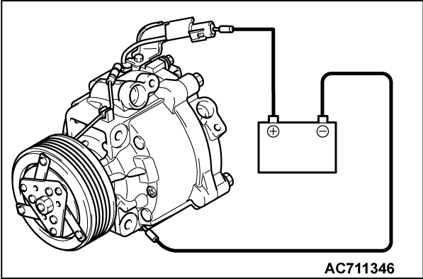
STEP 4. Check the A/C compressor clutch operation.
Connect the compressor connector terminal to the battery positive (+) terminal and ground the battery's negative (-) terminal to the compressor unit. At that time, the A/C compressor clutch should make a definite operating sound.
Can the sound (click) of the A/C compressor clutch operation be heard?
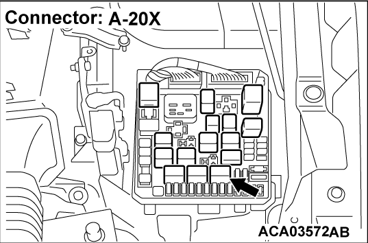
STEP 5. Check A/C compressor clutch relay connector A-20X for loose, corroded or damaged terminals, or terminals pushed back in the connector.
Is A/C compressor clutch relay connector A-20X in good condition?
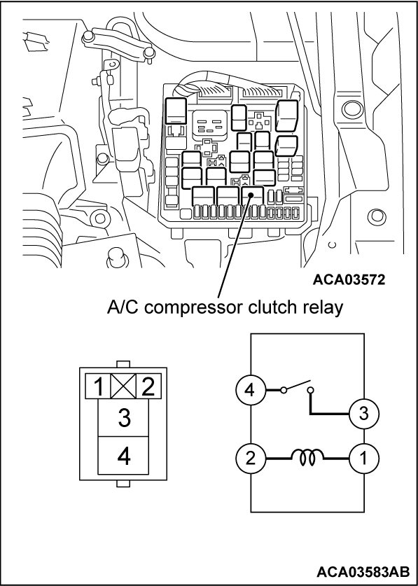
STEP 6. Check the A/C compressor clutch relay continuity.
Follow the table below to check the A/C compressor clutch relay for continuity.
 Replace the A/C compressor clutch relay.
|
Is the A/C compressor clutch relay in good condition?
 Replace the A/C compressor clutch relay.
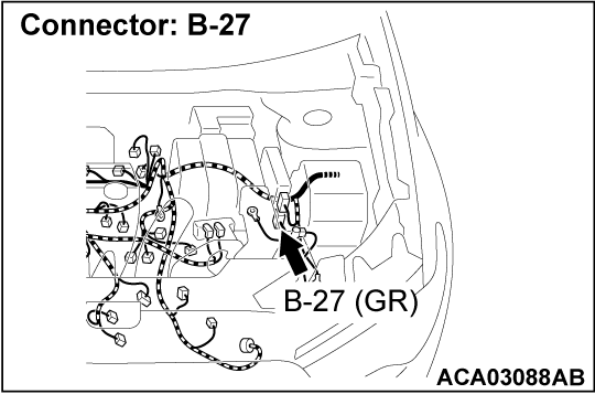
 STEP 7. Check engine control module connector B-27 for loose, corroded or damaged terminals, or terminals pushed back in the connector.
Is engine control module connector B-27 in good condition?
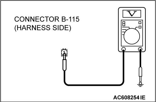
STEP 8. Measure the voltage at A/C compressor and clutch assembly connector B-115.
(1) Disconnect A/C compressor and clutch assembly connector B-115 and measure the voltage at the wiring harness side.
(2) Disconnect engine control module connector B-27 and ground harness side terminal No.102.
(3) Turn the ignition switch to the "ON" position.
(4) A/C compressor and clutch assembly connector B-115 terminal 1 and ground.
- The measured value should be approximately 12 volts (battery positive voltage).
Is the measured voltage approximately 12 volts?
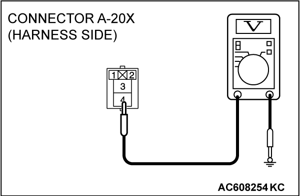
STEP 9. Measure the voltage at A/C compressor clutch relay connector A-20X.
(1) Disconnect A/C compressor clutch relay connector A-20X and measure the voltage at the relay box side.
(2) Turn the ignition switch to the "ON" position.
(3) Measure the voltage between terminal 4 and ground.
- The measured value should be approximately 12 volts (battery positive voltage).
(4) Measure the voltage between terminal 2 and ground.
- The measured value should be approximately 12 volts (battery positive voltage).
Is the measured voltage approximately 12 volts?
STEP 10. Check the wiring harness between A/C compressor clutch relay connector A-20X (terminals 2 and 4) and the fusible link (36).
- Check the A/C compressor clutch relay power supply line for open circuit.
Is the wiring harness between A/C compressor clutch relay connector A-20X (terminals 2 and 4) and the fusible link (36) in good condition?
 It can be assumed that this malfunction is intermittent. Refer to GROUP 00, How to Use Troubleshooting/Inspection Service Points - How to Cope with Intermittent Malfunctions
  .
. Repair the wiring harness. Check that the A/C works normally.
STEP 11. Check the wiring harness between A/C compressor clutch relay connector A-20X (terminal 3) and A/C compressor and clutch assembly connector B-115 (terminal 1).
- Check the A/C compressor assembly power supply line for open circuit.
Is the wiring harness between A/C compressor clutch relay connector A-20X (terminal 3) and A/C compressor and clutch assembly connector B-115 (terminal 1) in good condition?
 Repair the wiring harness. Check that the A/C works normally.
STEP 12. Check the wiring harness between engine control module connector B-27 (terminal 102) and A/C compressor clutch relay connector A-20X (terminal 1).
- Check the powertrain control module signal line for open and short circuit.
Is the wiring harness between engine control module connector B-27 (terminal 102) and A/C compressor clutch relay connector A-20X (terminal 1) in good condition?
 It can be assumed that this malfunction is intermittent. (Refer to GROUP 00, How to Use Troubleshooting/Inspection Service Points - How to Cope with Intermittent Malfunctions
  ).
). Repair the wiring harness. Check that the A/C works normally.
STEP 13. Replace the A/C control panel.
Does the A/C operate normally?
 No action is necessary and testing is complete.
![[Previous]](../../../buttons/fprev.png)
![[Next]](../../../buttons/fnext.png)
