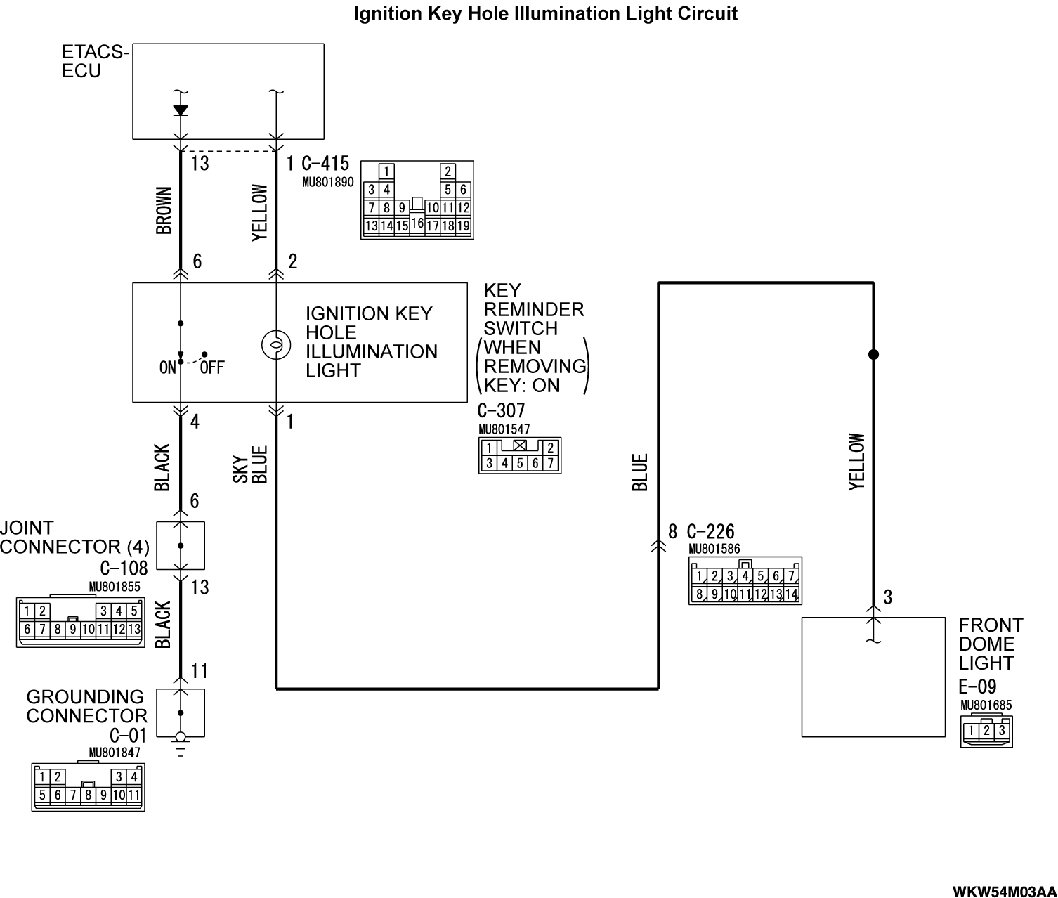
Inspection Procedure 1: The ignition key hole illumination light does not illuminate/extinguish normally.
| caution | Whenever the ECU is replaced, ensure that the input and output signal circuits are normal. |
OPERATION
The ETACS-ECU operates this function in accordance with the input signals below.
- Ignition switch (IG1)
- Key reminder switch
- Driver's door switch
- Driver's door lock actuator
TECHNICAL DESCRIPTION (COMMENT)
If this function does not work normally, these input signal circuit(s), the ignition key hole illumination light or the ETACS-ECU may be defective.
TROUBLESHOOTING HINTS
- The key reminder switch may be defective
- The driver's door switch may be defective
- The driver's door lock actuator may be defective
- The ignition key hole illumination light bulb may be defective
- The ETACS-ECU may be defective
- The wiring harness or connectors may have loose, corroded, or damaged terminals, or terminals pushed back in the connector
DIAGNOSIS
STEP 1. Using scan tool MB991958, read the diagnostic trouble code.
(1)
| caution | To prevent damage to scan tool MB991958, always turn the ignition switch to the "LOCK" (OFF) position before connecting or disconnecting scan tool MB991958. |
(2) Turn the ignition switch to the "ON" position.
(3) Check whether the ETACS-ECU related DTC is set.
(4) Turn the ignition switch to the "LOCK" (OFF) position.
Is the DTC set?
STEP 2. Using scan tool MB991958, check data list.
Use the ETACS-ECU data list to check the signals related to the ignition key hole illumination light function.
 <Normal condition is not displayed for item No. 228> : Troubleshoot the ETACS-ECU. Refer to Inspection Procedure 4 "ETACS-ECU cannot receive the signal of front door lock actuator (LH) or front door lock actuator (RH)."
  .
. <Normal condition is not displayed for item No. 254> : Troubleshoot the ETACS-ECU. Refer to Inspection Procedure 2 "ETACS-ECU does not receive any signal from the ignition switch (IG1)."
  .
. <Normal condition is not displayed for item No. 256> : Troubleshoot the ETACS-ECU. Refer to Inspection Procedure 5 "ETACS-ECU does not receive any signal from the front door switch (LH)."
  .
.
- Turn the ignition switch to the LOCK "(OFF)" position.
- Remove the ignition key from the ignition key hole.
- Open the driver's door.
|
Does scan tool MB991958 display the items "Dr door unlock", "Dr door ajar switch", and "Handle lock switch" as normal condition?
 <Normal condition is not displayed for item No. 228> : Troubleshoot the ETACS-ECU. Refer to Inspection Procedure 4 "ETACS-ECU cannot receive the signal of front door lock actuator (LH) or front door lock actuator (RH)."
  .
. <Normal condition is not displayed for item No. 254> : Troubleshoot the ETACS-ECU. Refer to Inspection Procedure 2 "ETACS-ECU does not receive any signal from the ignition switch (IG1)."
  .
. <Normal condition is not displayed for item No. 256> : Troubleshoot the ETACS-ECU. Refer to Inspection Procedure 5 "ETACS-ECU does not receive any signal from the front door switch (LH)."
  .
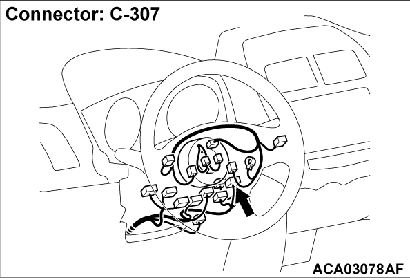
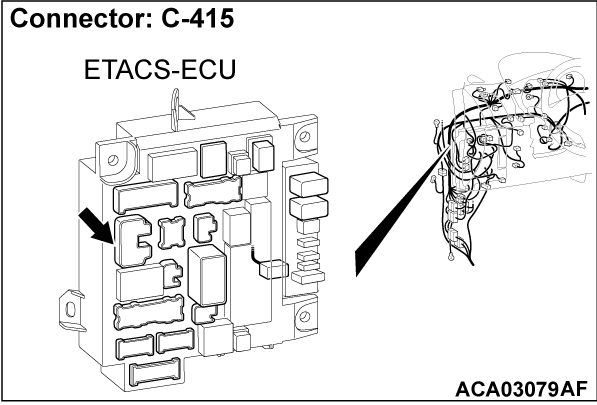
.STEP 3. Check key reminder switch connector C-307, ETACS-ECU connector C-415 for loose, corroded or damaged terminals, or terminals pushed back in the connector.
Is key reminder switch connector C-307, ETACS-ECU connector C-415 in good condition?
 Repair the damaged parts.
STEP 4. Check the wiring harness between key reminder switch connector C-307 (terminal No. 2) and ETACS-ECU connector C-415 (terminal No. 1).
- Check the input/output line for open circuit.
Is the check result normal?
 Repair the wiring harness between key reminder switch connector C-307 and ETACS-ECU connector C-415.
STEP 5. Check of ignition key hole illumination light bulb
Is the ignition key hole illumination light bulb in good condition?
 Replace the bulb of the ignition key hole illumination light.
STEP 6. Check the wiring harness between key reminder switch connector C-307 (terminal No. 4) and ground.
| note | Before the wiring harness check, check the joint connector C-108 and grounding connector C-01, and repair them if necessary. |
- Check the ground line for open circuit.
Is the check result normal?
 Repair the wiring harness between key reminder switch connector C-307 and ground.
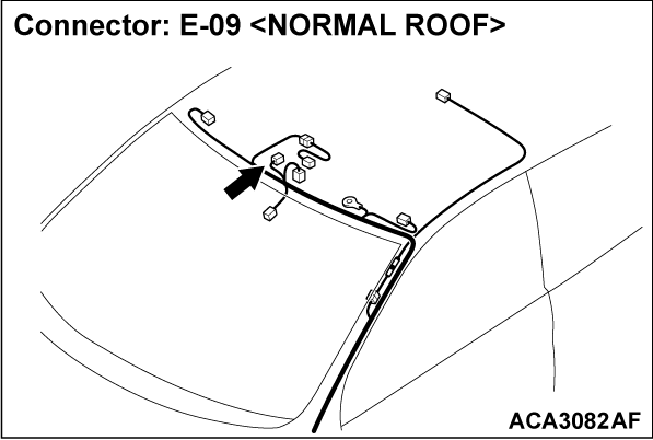
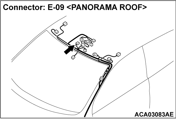
STEP 7. Check the wiring harness between key reminder switch connector C-307 (terminal No. 1) and front dome light connector E-09 (terminal No. 3).
| note | Before the wiring harness check, check the intermediate connector C-226, and repair them if necessary. |
- Check the ground line for open circuit.
Is the check result normal?
 Repair the wiring harness between key reminder switch connector C-307 and front dome light connector E-09.
![[Previous]](../../../buttons/fprev.png)
![[Next]](../../../buttons/fnext.png)
