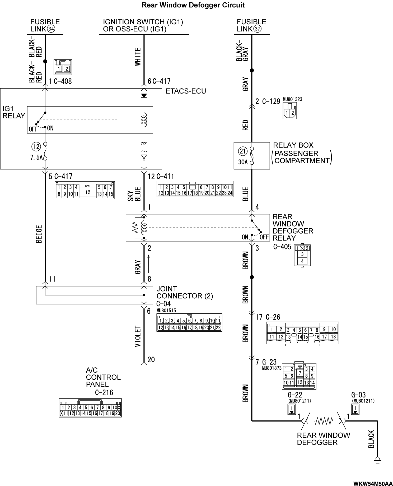
Rear window defogger does not operate.
TECHNICAL DESCRIPTION (COMMENT)
The rear window defogger is able to turn on while engine is running. If the defogger does not operate when the rear window defogger switch is turned on, the rear window defogger relay system may be defective.
TROUBLESHOOTING HINTS
- The A/C control panel may be defective.
- The rear window defogger relay may be defective.
- The ETACS-ECU may be defective.
- Damaged harness wires or connectors
DIAGNOSIS
Required Special Tools:
- MB991223: Harness Set
- MB992006: Extra Fine Probe
STEP 1. Using scan tool MB991958, diagnose the CAN bus line.
(1)
| caution | To prevent damage to scan tool MB991958, always turn the ignition switch to the "LOCK" (OFF) position before connecting or disconnecting scan tool MB991958. |
(2) Turn the ignition switch to the "ON" position.
(3) Diagnose the CAN bus line.
(4) Turn the ignition switch to the "LOCK" (OFF) position.
Is the CAN bus line found to be normal?
STEP 2. Check the A/C and outside/inside air selection damper control motor operation.
(1) Turn the ignition switch to the "ON" position.
(2) Check the engine running.
(3) Check the operations of outside/inside air selection damper control motor and A/C.
Do the A/C and outside/inside air selection damper control motor work normally?
STEP 3. Using scan tool MB991958, read the A/C control panel diagnostic trouble code.
Check that the A/C control panel has not set a DTC.
Is the DTC set?
STEP 4. Using scan tool MB991958, read the ETACS-ECU diagnostic trouble code.
Check that the ETACS-ECU has not set a DTC.
Is the DTC set?
STEP 5. Using scan tool MB991958, check data list.
Use the A/C control panel data list to check the signals related to the rear window defogger switch.
 Replace the A/C control panel.
- Start the engine.
- Turn the rear window defogger switch from off to on.
|
Does scan tool MB991958 display the items "ON", and "OFF" as normal condition?
 Replace the A/C control panel.
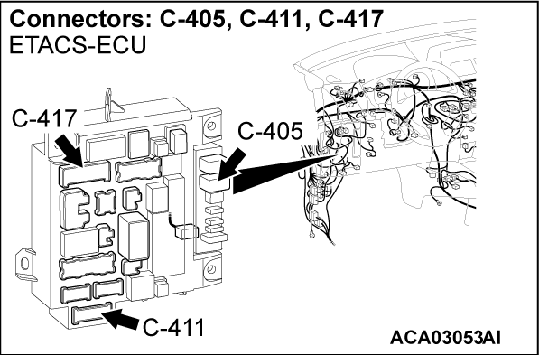
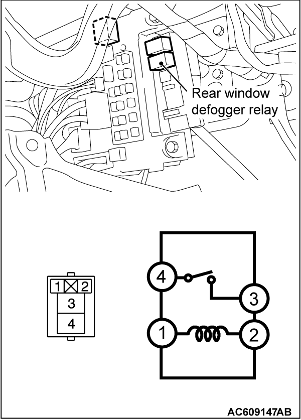
STEP 6. Check rear window defogger relay connector C-405 for loose, corroded or damaged terminals, or terminals pushed back in the connector.
Is rear window defogger relay connector C-405 in good condition?
STEP 7. Check the rear window defogger relay continuity.
Follow the table below to check the rear window defogger relay for continuity.
 Replace the rear window defogger relay. The rear window defogger system should work normally.
|
Is the rear window defogger relay in good condition?
 Replace the rear window defogger relay. The rear window defogger system should work normally.
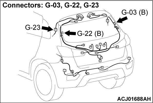
STEP 8. Check rear window defogger connector G-22 for loose, corroded or damaged terminals, or terminals pushed back in the connector.
Are rear window defogger connector G-22 in good condition?
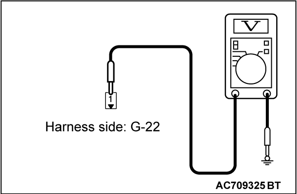
STEP 9. Measure the voltage at rear window defogger connector G-22.
(1) Disconnect rear window defogger connector G-22, and measure the voltage at the harness side.
(2) Start the engine.
(3) Rear window defogger switch: ON (measure within 20 minutes after the switch is turned on)
(4) Measure the voltage between rear window defogger connector G-22 terminal No.1 and ground.
- The measured value should be approximately 12 volts (battery positive voltage).
Is the measured voltage approximately 12 volts?
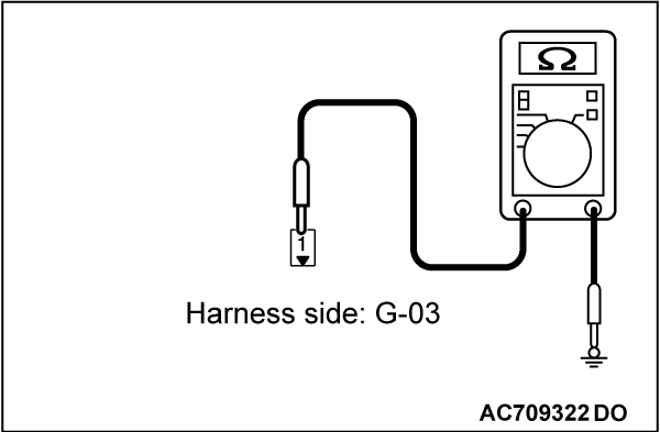
STEP 10. Measure the resistance at rear window defogger connector G-03.
(1) Disconnect rear window defogger connector G-03, and measure at the wiring harness side.
(2) Measure the resistance between terminal 1 and ground.
- The measured value should be 2 Ω or less.
Does the measured resistance value correspond with this range?
 Repair the wiring harness. Check that the rear window defogger system works normally.
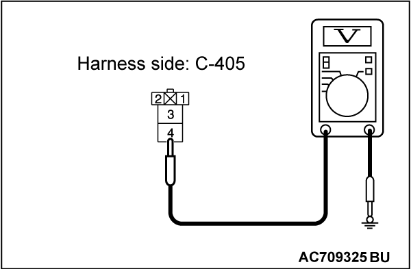
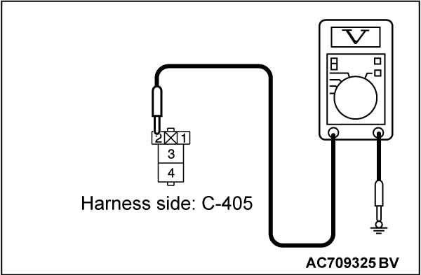
STEP 11. Measure the voltage at rear window defogger relay connector C-405.
(1) Disconnect rear window defogger relay connector C-405, and measure the voltage at the junction block side.
(2) Measure the voltage between terminal 4 and ground.
- The measured value should be approximately 12 volts (battery positive voltage).
Is the measured voltage approximately 12 volts?
STEP 12. Check the wiring harness between rear window defogger relay connector C-405 (terminal 4) and the fusible link (37).
Is the wiring harness between rear window defogger relay connector C-405 (terminal 4) and the fusible link (37) in good condition?
 The trouble can be an intermittent malfunction (Refer to GROUP 00, How to Cope with Intermittent Malfunction
  ).
). Repair the wiring harness. Check that the rear window defogger system works normally.
STEP 13. Measure the voltage at rear window defogger relay connector C-405.
(1) Disconnect rear window defogger relay connector C-405, and measure the voltage at the junction block side.
(2) Turn the ignition switch to the "ON" position.
(3) Measure the voltage between terminal 2 and ground.
- The measured value should be approximately 12 volts (battery positive voltage).
Is the measured voltage approximately 12 volts?
STEP 14. Check ETACS-ECU connector C-411 for loose, corroded or damaged terminals, or terminals pushed back in the connector.
Is ETACS-ECU connector C-411 in good condition?
STEP 15. Check the wiring harness between rear window defogger relay connector C-405 (terminal 1) and ETACS-ECU C-411 (terminal 12).
Is the wiring harness between rear window defogger relay connector C-405 (terminal 1) and ETACS-ECU connector C-411 (terminal 12) in good condition?
 Replace the ETACS-ECU.
 Repair the wiring harness. Check that the rear window defogger system works normally.
STEP 16. Check the wiring harness between rear window defogger relay connector C-405 (terminal 2) and ETACS-ECU connector C-417 (terminal 5).
- Check the wiring harness for open circuit and short circuit.
Is the wiring harness between rear window defogger relay connector C-405 (terminal 2) and ETACS-ECU connector C-417 (terminal 5) in good condition?
STEP 17. Check the wiring harness between rear window defogger relay connector C-405 (terminal 3) and rear window defogger connector G-22 (terminal 1).
Is the wiring harness between rear window defogger relay connector C-405 (terminal 3) and rear window defogger connector G-22 (terminal 1) in good condition?
 Replace the ETACS-ECU.
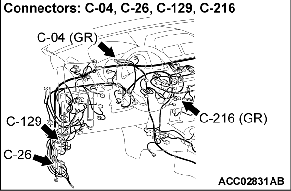
STEP 18. Check A/C control panel connector C-216 for loose, corroded or damaged terminals, or terminals pushed back in the connector.
Is A/C-ECU connector C-210 in good condition?
STEP 19. Check the wiring harness between rear window defogger relay connector C-405 (terminal 2) and A/C control panel connector C-216 (terminal 20).
- Check the wiring harness for open circuit and short circuit.
Are the wiring harness between rear window defogger relay connector C-405 (terminal 2) and A/C control panel connector C-216 (terminal 20) in good condition?
STEP 20. Check the rear window defogger.
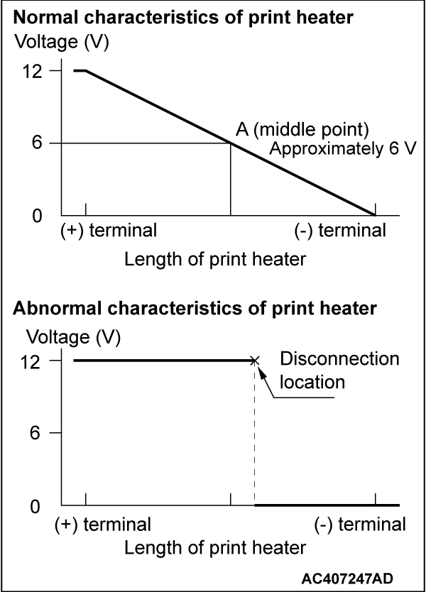
(1) Let the engine run at 2,000 r/min, and check the printed heater with the battery fully charged.
(2) Turn on the rear window defogger switch, and use a voltmeter to measure the voltage in each printed heater at middle point A on the rear window glass.
- The value should be approximately 6 volts.
Does the rear window defogger work normally?
 Replace the rear window defogger.
![[Previous]](../../../buttons/fprev.png)
![[Next]](../../../buttons/fnext.png)
