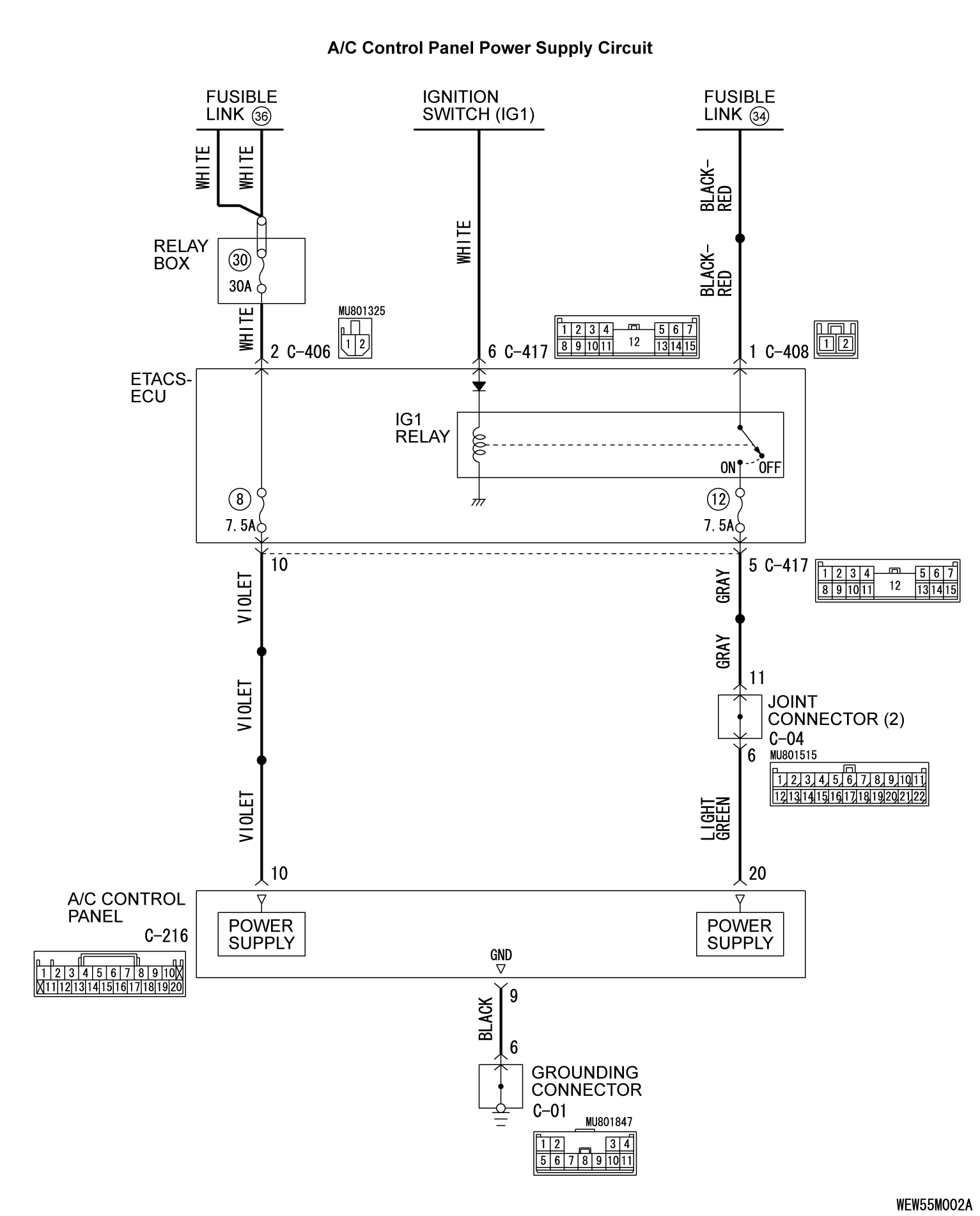
INSPECTION PROCEDURE 2: Malfunction of the A/C control panel Power Supply System.
TECHNICAL DESCRIPTION (COMMENT)
The A/C control panel power system may be defective if the air conditioning, defogger, and outside/inside air selection damper motor all do not operate normally.
TROUBLESHOOTING HINTS
- Malfunction of the A/C control panel
- Damaged wiring harness or connectors
DIAGNOSIS
Required Special Tool:
- MB991223: Harness Set
- MB992006: Extra Fine Probe
STEP 1. Check A/C control panel connector C-210 for loose, corroded or damaged terminals, or terminals pushed back in the connector.
Is A/C control panel connector C-210 in good condition?
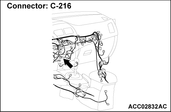
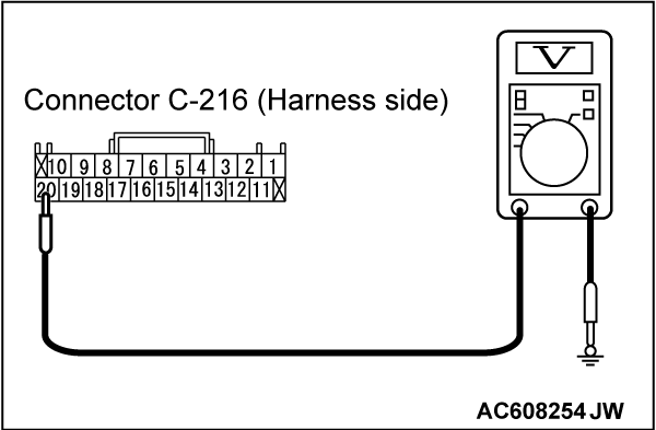
STEP 2. Measure the voltage at A/C control panel connector C-216.
(1) Disconnect A/C control panel connector C-216 and measure the voltage at the harness side.
(2) Turn the ignition switch to the "ON" position.
(3) Measure the voltage between terminal 20 and ground.
- The measured value should be approximately 12 volts (battery positive voltage).
Is the measured voltage approximately 12 volts?
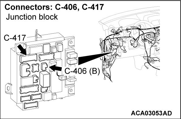
STEP 3. Check ETACS-ECU connector C-417 for loose, corroded or damaged terminals, or terminals pushed back in the connector.
Is ETACS-ECU connector C-417 in good condition?
STEP 4. Check the wiring harness between A/C control panel connector C-216 (terminal 20) and ETACS-ECU connector C-417 (terminal 5).
- Check the A/C control panel power supply line for open circuit.
Is the wiring harness between A/C control panel connector C-216 (terminal 20) and ETACS-ECU connector C-417 (terminal 5) in good condition?
 It can be assumed that this malfunction is intermittent. Refer to GROUP 00, How to Use Troubleshooting/Inspection Service Points - How to Cope with Intermittent Malfunctions
  .
. Repair the wiring harness. Check that the A/C works normally.
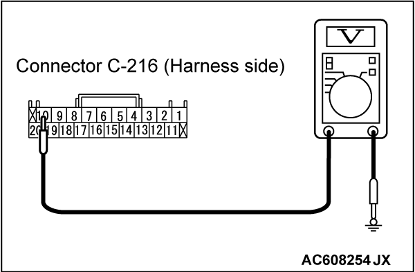
STEP 5. Measure the voltage at A/C control panel connector C-216.
(1) Disconnect A/C control panel connector C-216 and measure the voltage at the harness side.
(2) Measure the voltage between terminal 10 and ground.
- The measured value should be approximately 12 volts (battery positive voltage).
Is the measured voltage approximately 12 volts?
STEP 6. Check the wiring harness between A/C control panel connector C-216 (terminal 10) and the fusible link (36).
- Check the A/C control panel power supply line for open circuit.
Is the wiring harness between A/C control panel connector C-210 (terminal 13) and the fusible link (36) in good condition?
 It can be assumed that this malfunction is intermittent. Refer to GROUP 00, How to Use Troubleshooting/Inspection Service Points - How to Cope with Intermittent Malfunctions
  .
. Repair the wiring harness. Check that the A/C works normally.
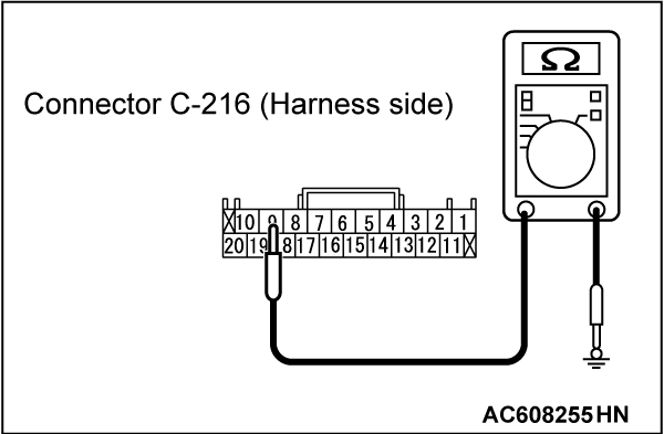
STEP 7. Measure the resistance at A/C control panel connector C-216.
(1) Disconnect A/C control panel connector C-216, and measure at the wiring harness side.
(2) Measure the resistance between terminal 9 and ground.
- The measured value should be 2 ohms or less.
Does the measured resistance value correspond with this range?
 Replace the A/C control panel, and check that the A/C works normally.
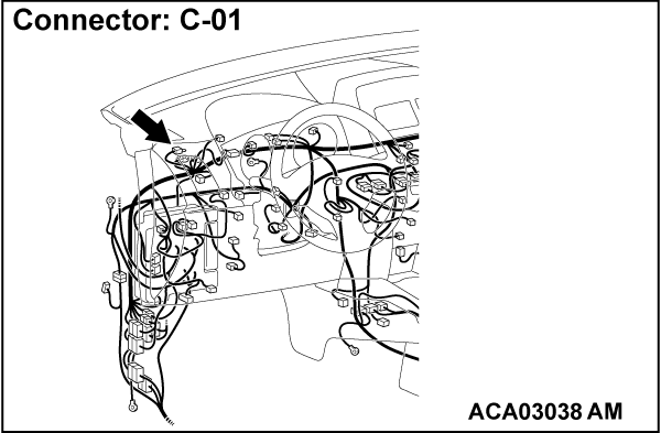
STEP 8. Check grounding connector C-01 for loose, corroded or damaged terminals, or terminals pushed back in the connector.
Is grounding connector C-01 in good condition?
STEP 9. Check the wiring harness between A/C control panel connector C-216 (terminal 9) and grounding connector C-01 (terminal 6).
- Check the A/C control panel ground line for open circuit.
Is the wiring harness between A/C control panel connector C-216 (terminal 9) and grounding connector C-01 (terminal 6) in good condition?
 It can be assumed that this malfunction is intermittent. Refer to GROUP 00, How to Use Troubleshooting/Inspection Service Points - How to Cope with Intermittent Malfunctions
  .
. Repair the wiring harness. Check that the A/C works normally.
![[Previous]](../../../buttons/fprev.png)
![[Next]](../../../buttons/fnext.png)
