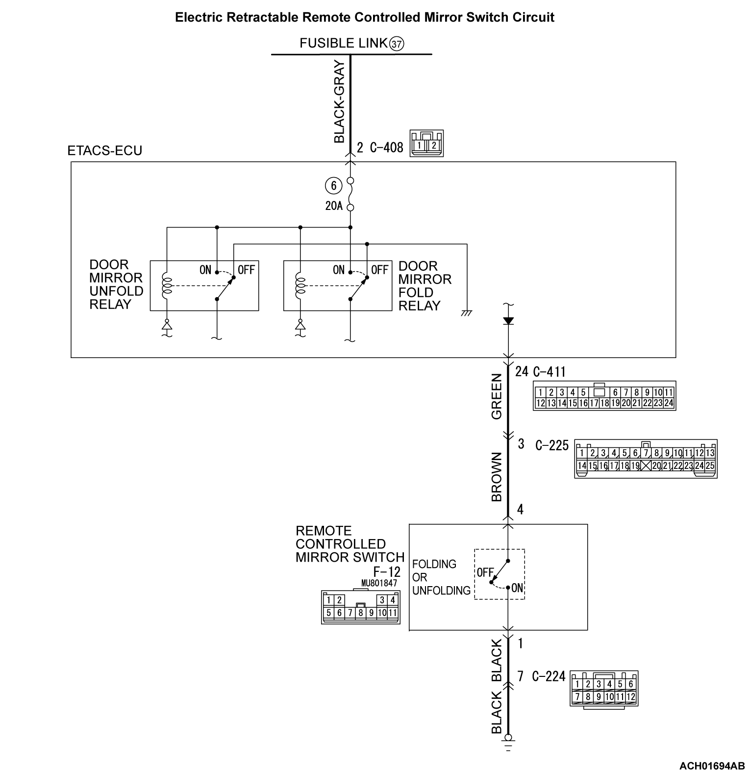
INSPECTION PROCEDURE 1: Electric-folding door mirrors do not work at all.
| caution | Before replacing the ECU, ensure that the power supply circuit, the ground circuit and the communication circuit are normal. |
CIRCUIT OPERATION
The ETACS-ECU operates this function in accordance with the input signals below.
- Ignition switch (ACC)
- Electric remote controlled mirror switch (folding/unfolding switch)
TECHNICAL DESCRIPTION (COMMENT)
If the system does not work, the input circuit from the ignition switch (ACC) or the remote controlled mirror switch (folding/unfolding switch), or the ETACS-ECU may be faulty.
TROUBLESHOOTING HINTS
- Defective remote controlled mirror switch
- Defective ignition switch (ACC)
- Malfunction of ETACS-ECU
- Damaged wiring harness and connectors
DIAGNOSIS
Required Special Tools:
- MB991223: Harness Set
- MB992006: Extra Fine Probe
STEP 1. Use the scan tool MB991958 to check if an ETACS-related diagnostic trouble code is set.
Check if an ETACS-related diagnosis trouble code is set.
Is the diagnostic trouble code set?
STEP 2. Check the input signals which controls the remote controlled mirror switch.
- Ignition switch: ACC
- Operate the remote controlled mirror switch.
|
OK: Normal condition is displayed.
Is the check result normal?
STEP 3. Check the input signals which controls the remote controlled mirror switch.
- Turn on the folding/unfolding switch when the door mirrors are folded.
|
- Turn on the folding/unfolding switch when the door mirrors are unfolded.
|
OK: Normal condition is displayed.
Is the check result normal?
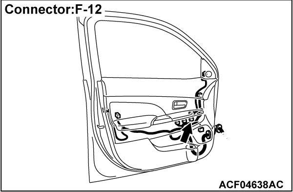
STEP 4. Check the remote controlled mirror switch connector F-12 for loose, corroded or damaged terminals, or terminals pushed back in the connector.
Is the remote controlled mirror switch connector F-12 in good condition?
 Repair the damaged connector.
STEP 5. Check the remote controlled mirror switch.
Check that the remote controlled mirror switch is normal (Refer to  ).
). Replace the remote controlled mirror switch.
 ).
).Is the check result normal?
 Replace the remote controlled mirror switch.
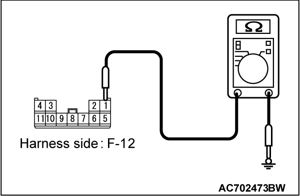
STEP 6. Measure the resistance at the F-12 remote controlled mirror switch connector.
(1) Disconnect the connector, and measure the resistance at the wiring harness-side connector.
(2) Measure the resistance between F-12 remote controlled mirror switch connector terminal No. 1 and body ground.
OK: Continuity (2 Ω or less)
Is the check result normal?
STEP 7. Check the wiring harness between F-12 remote controlled mirror switch connector terminal No. 1 and body ground.
- Check the ground wires for open circuit.
Is the wiring harness between F-12 remote controlled mirror switch connector terminal No. 1 and body ground in good condition?
 Intermittent malfunction (Refer to GROUP 00 - How to Use Troubleshooting/Inspection Service Points - How to Cope with Intermittent Malfunction
  .)
.) Repair the wiring harness.
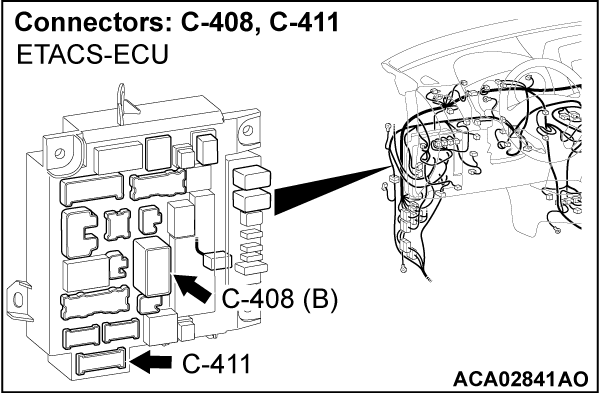
STEP 8. Check the ETACS-ECU connector C-411 for loose, corroded or damaged terminals, or terminals pushed back in the connector.
STEP 9. Check the wiring harness between C-411 ETACS-ECU connector terminal No. 24 and F-12 remote controlled mirror switch connector terminal No. 4.
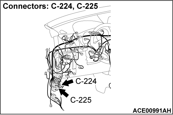
| note | Prior to the wiring harness inspection, check the C-225 intermediate connector, and repair if necessary. |
- Check the power supply line for open circuit or short circuit.
Is the wiring harness between C-408 ETACS-ECU connector terminal No. 24 and F-12 remote controlled mirror switch connector terminal No. 4 in good condition?
 Repair the wiring harness.
STEP 10. Check the ETACS-ECU connector C-408 for loose, corroded or damaged terminals, or terminals pushed back in the connector.
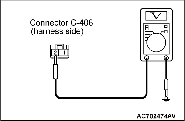
STEP 11. Measure the voltage at the C-408 ETACS-ECU connector.
(1) Disconnect the C-408 ETACS-ECU connector, and measure the voltage at the wiring harness-side connector.
(2) Measure the voltage between C-408 ETACS-ECU connector terminal No. 2 and body ground.
OK: System voltage
Is the check result normal?
STEP 12. Check the wiring harness between C-408 ETACS-ECU connector terminal No. 2 and fusible link (37).
- Check the power supply line for open circuit.
Is the wiring harness between C-408 ETACS-ECU connector terminal No. 2 and fusible link (37) in good condition?
 Intermittent malfunction (Refer to GROUP 00 - How to Use Troubleshooting/Inspection Service Points - How to Cope with Intermittent Malfunction
  .)
.) Repair the wiring harness.
![[Previous]](../../../buttons/fprev.png)
![[Next]](../../../buttons/fnext.png)
