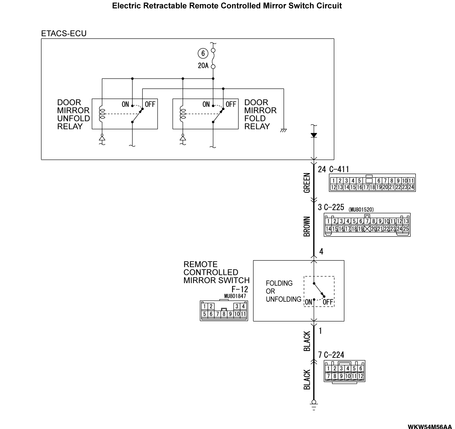
Inspection Procedure 14: ETACS-ECU does not receive any signal from the remote controlled mirror switch (fold switch).
TECHNICAL DESCRIPTION (COMMENT)
Input signal from the remote controlled mirror switch (fold switch) is used to operate the functions below. If the signal is abnormal, these functions will not work normally.
- Electric-folding door mirrors
TROUBLESHOOTING HINTS
- The remote controlled mirror switch may be defective
- The ETACS-ECU may be defective
- The wiring harness or connectors may have loose, corroded, or damaged terminals, or terminals pushed back in the connector
DIAGNOSIS
Required Special Tools:
- MB991223: Harness Set
- MB992006: Extra Fine Probe
STEP 1. Check the remote controlled mirror switch.
Refer to GROUP 51 - Door Mirror  .
. Replace the remote controlled mirror switch.
 .
.Is the check result normal?
 Replace the remote controlled mirror switch.
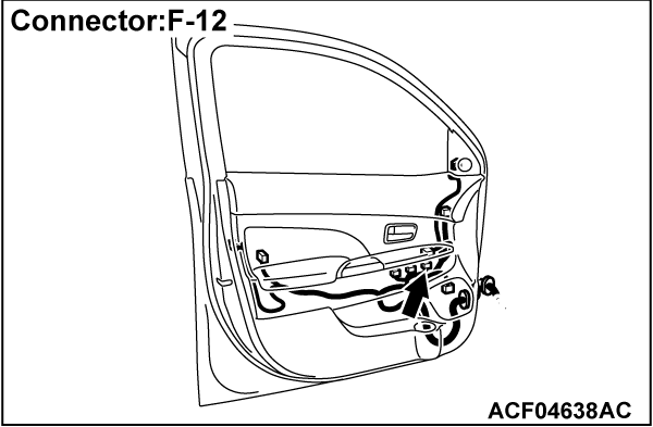
STEP 2. Check the remote controlled mirror switch connector F-12 for loose, corroded or damaged terminals, or terminals pushed back in the connector.
Is the remote controlled mirror switch connector F-12 in good condition?
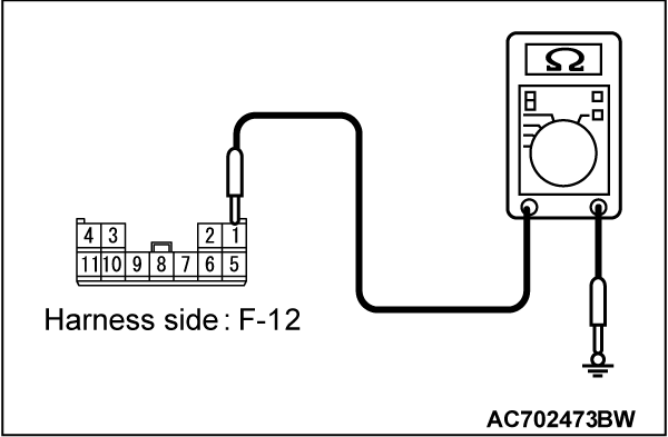
STEP 3. Measure the resistance at the F-12 remote controlled mirror switch connector.
(1) Disconnect the connector, and measure the resistance at the wiring harness-side connector.
(2) Measure the resistance between F-12 remote controlled mirror switch connector terminal No. 1 and body ground.
OK: The measured value should be continuity exists (2 ohms or less).
Is the check result normal?
STEP 4. Check the wiring harness between F-12 remote controlled mirror switch connector terminal No. 1 and body ground.
- Check the ground wires for open circuit.
Is the wiring harness between F-12 remote controlled mirror switch connector terminal No. 1 and body ground in good condition?
 The trouble can be an intermittent malfunction (Refer to GROUP 00 - How to use Troubleshooting/inspection Service Points - How to Cope with Intermittent Malfunction
  ).
). The wiring harness may be damaged or the connector(s) may have loose, corroded or damaged terminals, or terminals pushed back in the connector. Repair the wiring harness as necessary. Verify that the high-beam headlights illuminate normally.
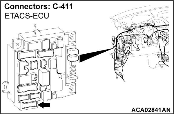
STEP 5. Check the ETACS-ECU connector C-411 for loose, corroded or damaged terminals, or terminals pushed back in the connector.
Is the ETACS-ECU connector C-411 in good condition?
STEP 6. Check the wiring harness between C-411 ETACS-ECU connector terminal No. 24 and F-12 remote controlled mirror switch connector terminal No. 4.
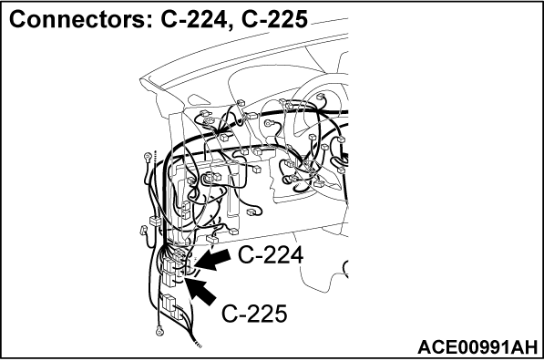
| note | Prior to the wiring harness inspection, check the C-225 intermediate connector, and repair if necessary. |
- Check the power supply line for open circuit or short circuit.
Is the wiring harness between C-411 ETACS-ECU connector terminal No. 24 and F-12 remote controlled mirror switch connector terminal No. 4 in good condition?
 The wiring harness may be damaged or the connector(s) may have loose, corroded or damaged terminals, or terminals pushed back in the connector. Repair the wiring harness as necessary. Verify that the high-beam headlights illuminate normally.
STEP 7. Using scan tool MB991958, check data list.
(1)
| caution | To prevent damage to scan tool MB991958, always turn the ignition switch to the "LOCK" (OFF) position before connecting or disconnecting scan tool MB991958. |
(2) Turn the ignition switch to the "ON" position.
(3) Check the input signals from the remote controlled mirror switch (fold switch).
- During the folding/unfolding switch is being pressed.
|
OK: Normal condition is displayed.
Is the check result normal?
 The trouble can be an intermittent malfunction (Refer to GROUP 00 - How to use Troubleshooting/inspection Service Points - How to Cope with Intermittent Malfunction
  ).
). Replace the ETACS-ECU.
![[Previous]](../../../buttons/fprev.png)
![[Next]](../../../buttons/fnext.png)
