INSPECTION
DOOR MIRROR ASSEMBLY OPERATION CHECK
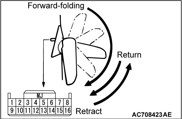
Remove the door trim, and then connect the battery to the door mirror assembly connector to check that the door mirror operates.
|
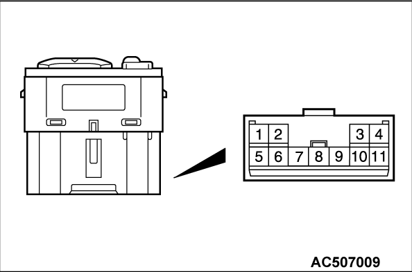
REMOTE CONTROLLED MIRROR SWITCH CONTINUITY CHECK
| |||||||||||||||||||||||||||
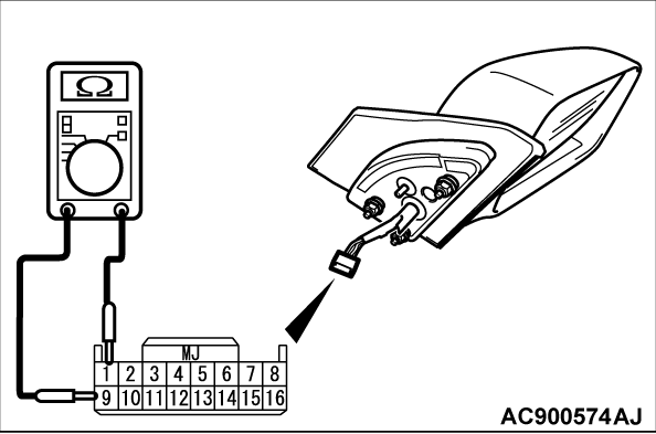
HEATED DOOR MIRROR CHECK
| caution | When relocating the car between locations with extremely different temperatures (warm and cold), leave the car in the location for a while to adapt to the temperature prior to checking it. |
Check that the resistance value between the connector terminals is at the standard value.
Standard value: 7.2 ± 1.4 Ω at 25°C (77°F)
BLIND SPOT WARNING LIGHT CHECK <VEHICLES WITH BSW>
Blind spot warning light check
1.
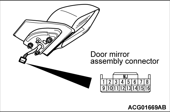
Apply 5V to the door mirror assembly connector terminal No. 3, ground the terminal No. 11, and then check that the illumination lights up.
| caution | Do not apply battery voltage to door mirror assembly connector No. 3 terminal as the blind spot warning light is broken. |
2.
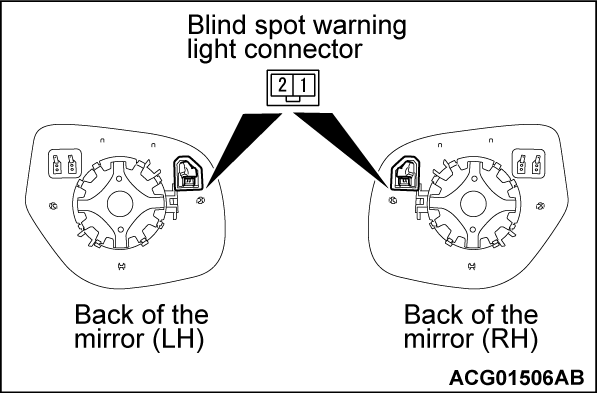
Apply 5V to the blind spot warning light connector terminal No. 1, ground the terminal No. 2, and then check that the illumination lights up.
| caution | Do not apply battery voltage to blind spot warning light connector No. 1 terminal as the blind spot warning light is broken. |
Checking the door mirror main wiring harness wires for continuity
Check the continuity between the door mirror assembly connector and the blind spot warning light connector.
|
![[Previous]](../../../buttons/fprev.png)
![[Next]](../../../buttons/fnext.png)
