![[Previous]](../../../BUTTONS/fprev.png)
![[Next]](../../../BUTTONS/fnext.png)
| DTC P0455 | Evaporative Emission Control System Leak Detected (Gross Leak) |
||||||||||||||||||||||||||||||||||||||||||||||||||||||||||||||||||||||||||||||
| DIAGNOSIS Required Special Tool: MB991502: Scan Tool (MUT-II) CAUTION: To prevent damage to scan tool MB991502, always turn the ignition switch to "LOCK" (OFF) position before connecting or disconnecting scan tool MB991502. In this procedure, scan tool MB991502 should be used in the metric mode (showing the value in kPa). If not, set scan tool MB991502 by selecting the "System Setup" at the main menu. |
|||||||||||||||||||||||||||||||||||||||||||||||||||||||||||||||||||||||||||||||
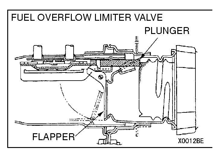
| STEP 1. Check the fuel overflow limiter valve plunger and flapper door operation. NOTE: The fuel overflow limiter valve plunger opens and closes in sequence with the flapper door and fuel overflow limiter valve plunger. When the fuel gun is inserted in the fuel filler neck and the flapper door is opened, the fuel overflow limiter valve plunger will close. (The fuel overflow limiter valve plunger will move to the top of the neck.) When the fuel cap is closed, the fuel cap pushes the fuel overflow limiter valve plunger and the fuel overflow limiter valve plunger opens. If the flapper door or fuel overflow limiter valve plunger does not operate correctly, the fuel overflow limiter valve plunger will remain closed even if the fuel cap is closed (same state as when the evaporator line is clogged). This can cause DTC P0455 to occur. |
|||||||||||||||||||||||||||||||||||||||||||||||||||||||||||||||||||||||||||||||
| (1)Remove the fuel cap. (2)Push the flapper with an ornament remover, etc., to activate the valve. NOTE: The fuel overflow limiter valve plunger moves upward when the flapper is pushed. (3)Tighten the fuel cap until three clicks are heard. |
|||||||||||||||||||||||||||||||||||||||||||||||||||||||||||||||||||||||||||||||
| (4)Remove the fuel cap again, and with the fuel overflow limiter valve plunger pushed in, measure the projection amount. (5)Confirm that the distance from the end of the fuel tank filler neck to the end of the fuel overflow limiter valve plunger is 28 mm (1.1 inches) or more. If the fuel overflow limiter valve plunger does not return completely [when less than 28mm (1.1 inches)], replace the fuel tank filler neck, completely tighten the fuel cap and perform OBD-II drive cycle. If the fuel overflow limiter valve plunger has completely returned [when 28 mm (1.1 inches) or more], completely tighten the fuel cap and go to Step 2. |
|||||||||||||||||||||||||||||||||||||||||||||||||||||||||||||||||||||||||||||||
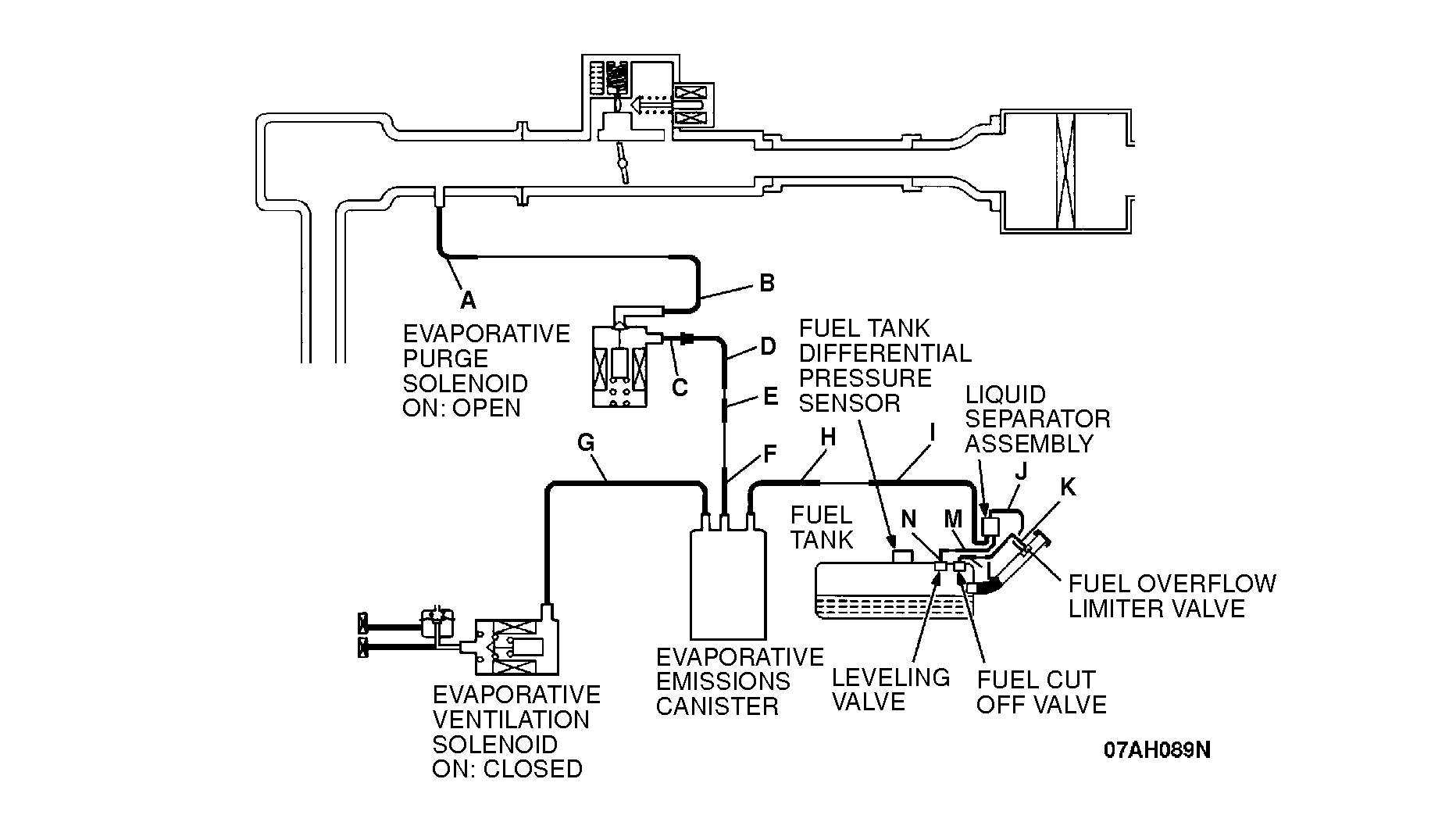
| STEP 2. Check for leaks in the evaporator line hose A and evaporative emission purge solenoid valve. (1)Disconnect hose A at the intake manifold side, and then connect a hand vacuum pump to the hose. (2)Apply vacuum. NOTE: The vacuum should be 40 kPa (5.8 psi) or less. If the vacuum is maintained, go to Step 5. If the vacuum leaks, go to Step 3. |
|||||||||||||||||||||||||||||||||||||||||||||||||||||||||||||||||||||||||||||||
| STEP 3. Check for leaks in the evaporator line hose A. Perform leakage test with a hand vacuum pump on hose A. If the location of the leak is pinpointed, replace that hose, and go to Step 22. If the location of the leak cannot be pinpointed, go to Step 4. |
|||||||||||||||||||||||||||||||||||||||||||||||||||||||||||||||||||||||||||||||
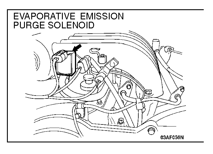
| STEP 4. Check the evaporative emission purge solenoid valve using the scan tool MB991502. (Actuator test item 08) (1)Turn the ignition switch "ON" position, and disconnect hose B from the evaporative emission purge solenoid side. (2)Connect the hand vacuum pump to the nipple of the evaporative emission purge solenoid from which the hoses have been disconnected. (3)Apply a vacuum on the hand vacuum pump, and confirm that the applied vacuum does not fluctuate. If the vacuum fluctuates, refer to the evaporative emission purge solenoid trouble code DTC P0443. (4)While maintaining the vacuum, carry out the actuator test with scan tool MB991502, and confirm that the atmospheric pressure is returned to when the evaporative emission purge solenoid is driven. If the evaporative emission purge solenoid operates correctly and the atmospheric pressure is returned to, go to Step 22. If the evaporative emission purge solenoid operates correctly, but the atmospheric pressure is not returned to, replace the evaporative emission purge solenoid, and then go to Step 22. If the evaporative emission purge solenoid does not operate, refer to the evaporative emission purge solenoid trouble code DTC P0443. |
|||||||||||||||||||||||||||||||||||||||||||||||||||||||||||||||||||||||||||||||
| STEP 5. Check for clogging in the evaporator line hose B and evaporative emission purge solenoid valve. Use scan tool MB991502 to activate evaporative emission purge solenoid valve. The vacuum should leak. If the vacuum leaks, go to Step 7. If the vacuum is maintained, go to Step 6. |
|||||||||||||||||||||||||||||||||||||||||||||||||||||||||||||||||||||||||||||||
| STEP 6. Check for clogging in the evaporator line hose A. Perform clogging test with a hand vacuum pump on hose A. If the clogging section is pinpointed, replace that hose, and perform the purge flow check (Refer to GROUP 17, Engine Emission Control) If the location of the leak cannot be pinpointed, go to Step 4. |
|||||||||||||||||||||||||||||||||||||||||||||||||||||||||||||||||||||||||||||||
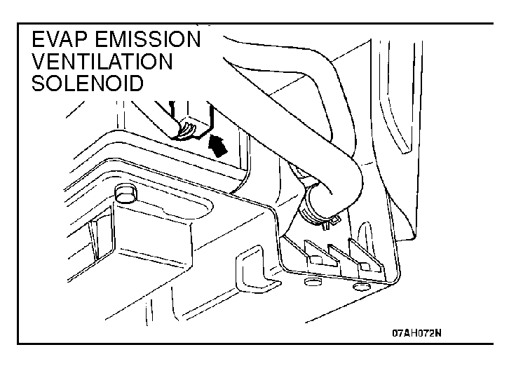
| STEP 7. Check the evaporative emission ventilation solenoid using the scan tool MB991502. (Actuator test item 29) (1)Lower the evaporative emission canister assembly, turn the ignition switch to "ON" position, and disconnect hose G from the evaporative emission ventilation solenoid side. (2)Connect the hand vacuum pump to the nipple of the evaporative emission ventilation solenoid from which the hoses have been disconnected. (3)Apply a vacuum on the hand vacuum pump, and confirm that pressure is applied. If the vacuum is maintained, refer to the evaporative emission ventilation solenoid trouble code DTC P0446. (4)Drive the evaporative emission ventilation solenoid with the scan tool MB991502 actuator test, and confirm that the vacuum does not fluctuate when the vacuum is applied with the hand vacuum pump. If the evaporative emission ventilation solenoid operates correctly and the applied vacuum does not fluctuate, go to Step 8. If the evaporative emission ventilation solenoid operates correctly, but the vacuum is not maintained, replace the evaporative emission ventilation solenoid, and then go to Step 22. If the evaporative emission ventilation solenoid does not operate, refer to the evaporative emission ventilation solenoid trouble code DTC P0446. |
|||||||||||||||||||||||||||||||||||||||||||||||||||||||||||||||||||||||||||||||
| STEP 8. Pressure test for evaporator line from hose C to hose G. (1)Using locking pliers, pinch hose G between the canister and the evaporative emission ventilation solenoid. (2)Confirm that the evaporative emission system pressure pump (Miller number 6872A) is operating properly. Perform the self-test as described in the manufacturer's instructions. |
|||||||||||||||||||||||||||||||||||||||||||||||||||||||||||||||||||||||||||||||
| (3)Connect an evaporative emission system pressure pump to the fuel filler neck. (4)Pressure test the system to determine whether any leaks are present. NOTE: "Pressure test" in this procedure refers to the I/M240 Simulation Test (8 simple steps) described in the evaporative emission system pressure pump (Miller number 6872A) manufacturer's instructions located in the lid of the pump box. If no leaks are indicated, go to Step 16. If a leak is indicated, go to Step 9. STEP 9. Pressure test for evaporator line from hose I to hose N. (1)Disconnect hose I from the liquid separator assembly and plug the hose and pipe which has been disconnected. (2)Perform the pressure test again. If no leaks are indicated, go to Step 10. If a leak is indicated, go to Step 12. |
|||||||||||||||||||||||||||||||||||||||||||||||||||||||||||||||||||||||||||||||
| STEP 10. Check for leaks in the evaporator line from hose C to hose G. Perform leakage test with a hand vacuum pump on each hose from hose C to G. If the location of the leak is pinpointed, replace that hose, and go to Step 22. If the location of the leak cannot be pinpointed, go to Step 11. |
|||||||||||||||||||||||||||||||||||||||||||||||||||||||||||||||||||||||||||||||
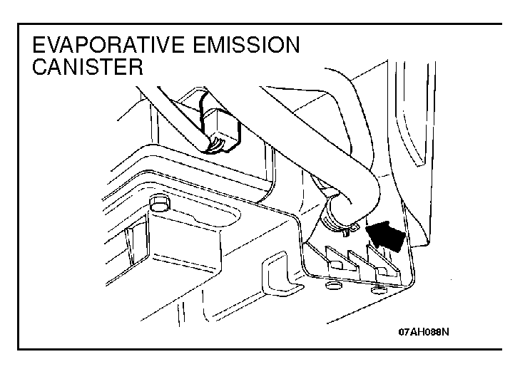
| STEP 11. Check for leaks in the evaporative emission canister. (1)Connect a hand vacuum pump to the vent nipple of the evaporative emission canister. (2)Plug the other two nipples or loop a hose between the other nipples. (3)Apply a vacuum with the hand vacuum pump, and confirm that the applied vacuum does not fluctuate. If the vacuum does not fluctuate, go to Step 22. If the applied vacuum fluctuates, replace the evaporative emission canister and then go to Step 22. |
|||||||||||||||||||||||||||||||||||||||||||||||||||||||||||||||||||||||||||||||
| STEP 12. Check for leaks in the evaporator line hoses I, J and K. Perform leakage test with a hand vacuum pump on hoses I, J and K.. If the location of the leak is pinpointed, replace that hose, and go to Step 22. If the location of the leak cannot be pinpointed, go to Step 13. STEP 13. Check for leaks in the evaporator line from hose L to hose N. (1)Remove the fuel tank. (Refer to GROUP 13F, Fuel Tank) (2)Perform leakage test with a hand vacuum pump on each hose from hose L to hose N. If the location of the leak is pinpointed, replace that hose, install the fuel tank. Then go to Step 22. If the location of the leak cannot be pinpointed, go to Step 14. |
|||||||||||||||||||||||||||||||||||||||||||||||||||||||||||||||||||||||||||||||
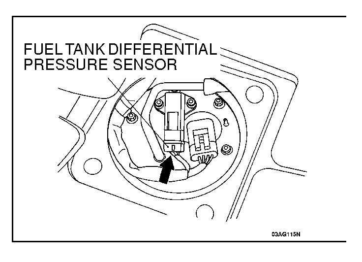
| STEP 14. Check for leaks in the fuel tank. (1)Visually check for cracks and leaks, etc. NOTE: Carefully check the fuel pump assembly and the inner pressure sensor installation section in the fuel tank. |
|||||||||||||||||||||||||||||||||||||||||||||||||||||||||||||||||||||||||||||||
| (4)Apply pressure with the evaporative emission system pressure pump. (5)In the pressurized state, check for the leak by applying soap water, etc. to each section. |
|||||||||||||||||||||||||||||||||||||||||||||||||||||||||||||||||||||||||||||||
| If the leak is at the fuel pump assembly or the inner pressure sensor installation section in the fuel tank: Reassemble the parts, check again that there are no leaks, reinstall the fuel tank, and go to Step 22. If the leak is at another section: Go to Step 15. |
|||||||||||||||||||||||||||||||||||||||||||||||||||||||||||||||||||||||||||||||
| STEP 15. Visually check for cracks in the fuel tank filler neck. Visually check for cracks in the fuel tank filler neck. If cracks are found, replace the fuel filler neck and go to Step 22. If no cracks are found go to Step 22. |
|||||||||||||||||||||||||||||||||||||||||||||||||||||||||||||||||||||||||||||||
| STEP 16. Check for clogging in the evaporator line from hose G to hose N. (1)Lower the evaporative emission canister assembly and disconnect hose G. (2)On the EVAP pressure pump, set the pressure/hold valve to OPEN, and set the vent valve to CLOSED. Turn the pump timer to ON. You can reset the timer as required. (These settings are listed under "Leak Test" in the pump instructions.) |
|||||||||||||||||||||||||||||||||||||||||||||||||||||||||||||||||||||||||||||||
| (3)Air should pass through hose G. If the air passes, go to Step 19. If the air does not pass, go to Step 17. |
|||||||||||||||||||||||||||||||||||||||||||||||||||||||||||||||||||||||||||||||
| STEP 17. Check for clogging in the evaporator line hose I. Perform clogging test with a hand vacuum pump on hose I. If the clogging section is pinpointed, replace that hose, and perform OBD-II drive cycle. If the clogging section cannot be pinpointed, go to Step 18. |
|||||||||||||||||||||||||||||||||||||||||||||||||||||||||||||||||||||||||||||||
| STEP 18. Check for clogging in the evaporator line from hose L to hose N. (1)Remove the fuel tank. (Refer to GROUP 13F, Fuel Tank) (2)Perform clogging test with a hand vacuum pump on each hose from hose L to hose N. If the clogging section is pinpointed, replace that hose, install the fuel tank, and perform OBD-II drive cycle. If the clogging section cannot be pinpointed, go to Step 22. |
|||||||||||||||||||||||||||||||||||||||||||||||||||||||||||||||||||||||||||||||
| STEP 19. Check for clogging in the evaporator line hose F to C. (1)Lower the evaporative emission canister assembly, disconnect hose F and connect a hand vacuum pump to the hose. (2)Apply vacuum. NOTE: The vacuum should be 40 kPa (5.8 psi) or less. (3)Use scan tool MB991502 to activate the evaporative emission purge solenoid valve. The vacuum should leak. If the vacuum leaks, perform OBD-II drive cycle. If the vacuum is maintained, go to Step 20. |
|||||||||||||||||||||||||||||||||||||||||||||||||||||||||||||||||||||||||||||||
| STEP 20. Check for clogging in the evaporator line hose C to hose G. Perform clogging test with a hand vacuum pump on each hose from hose C to hose G. If the clogging section is pinpointed, replace that hose, and perform OBD-II drive cycle. If the clogging section cannot be pinpointed, go to step 21. |
|||||||||||||||||||||||||||||||||||||||||||||||||||||||||||||||||||||||||||||||
| STEP 21. Check for clogging in the evaporative emission canister. (1)Connect a hand vacuum pump to the vent nipple of the evaporative emission canister. (2)Plug the other two nipples or loop a hose between the other nipples. (3)Apply vacuum. When each nipple is unplugged, the vacuum should fluctuate. If the applied vacuum fluctuates. Then go to Step 22. If the vacuum does not fluctuate, replace the evaporative emission canister, and perform OBD-II drive cycle. |
|||||||||||||||||||||||||||||||||||||||||||||||||||||||||||||||||||||||||||||||
| STEP 22. Evaporative Emission System Monitor Test using scan tool MB991502. (1)Turn the ignition switch to "ON" position. (2)Erase the DTCs using the scan tool MB991502. (3)Check that the fuel cap is securely closed. (Tighten until three clicks are heard.) (4)Start the engine. (5)Select "System Test," and press the "YES" key. (6)Select "Evap Leak Mon," and press the "YES" key. (7)During the monitor, keep the accelerator pedal at the idling position. NOTE: If the engine speed does not reach 2,000 r/min during the monitor test, adjustment of the Speed Adjusting Screw may be needed. Refer to (8)Keep the engine speed and engine load within the specified range. When the monitor test starts, the "In Progress" item on the scan tool MB991502 will change from "NO" to "YES." (9)The message "Evap Leak Mon. Completed Test Passed" displays when the test has been completed without malfunction. The evaporative emission system is working properly at this time. Explain to the customer that improperly tightened fuel cap can cause MIL to turn on, and return the vehicle. (10)The message "Evap Leak Mon. Completed. Test Failed and DTCs Set" displays when a malfunction has been detected during the monitor test. Go to Step 2. (11)The message "Evap Lead Mon. discontinued. Retest again from the first" is displayed when the monitor was discontinued for a certain reason (vehicle speed input from computer, engine speed and engine load deviating from specified range). Turn the ignition switch to the "LOCK" (OFF) position once, and repeat the monitoring from the start. |
|||||||||||||||||||||||||||||||||||||||||||||||||||||||||||||||||||||||||||||||