![[Previous]](../../../BUTTONS/fprev.png)
![[Next]](../../../BUTTONS/fnext.png)
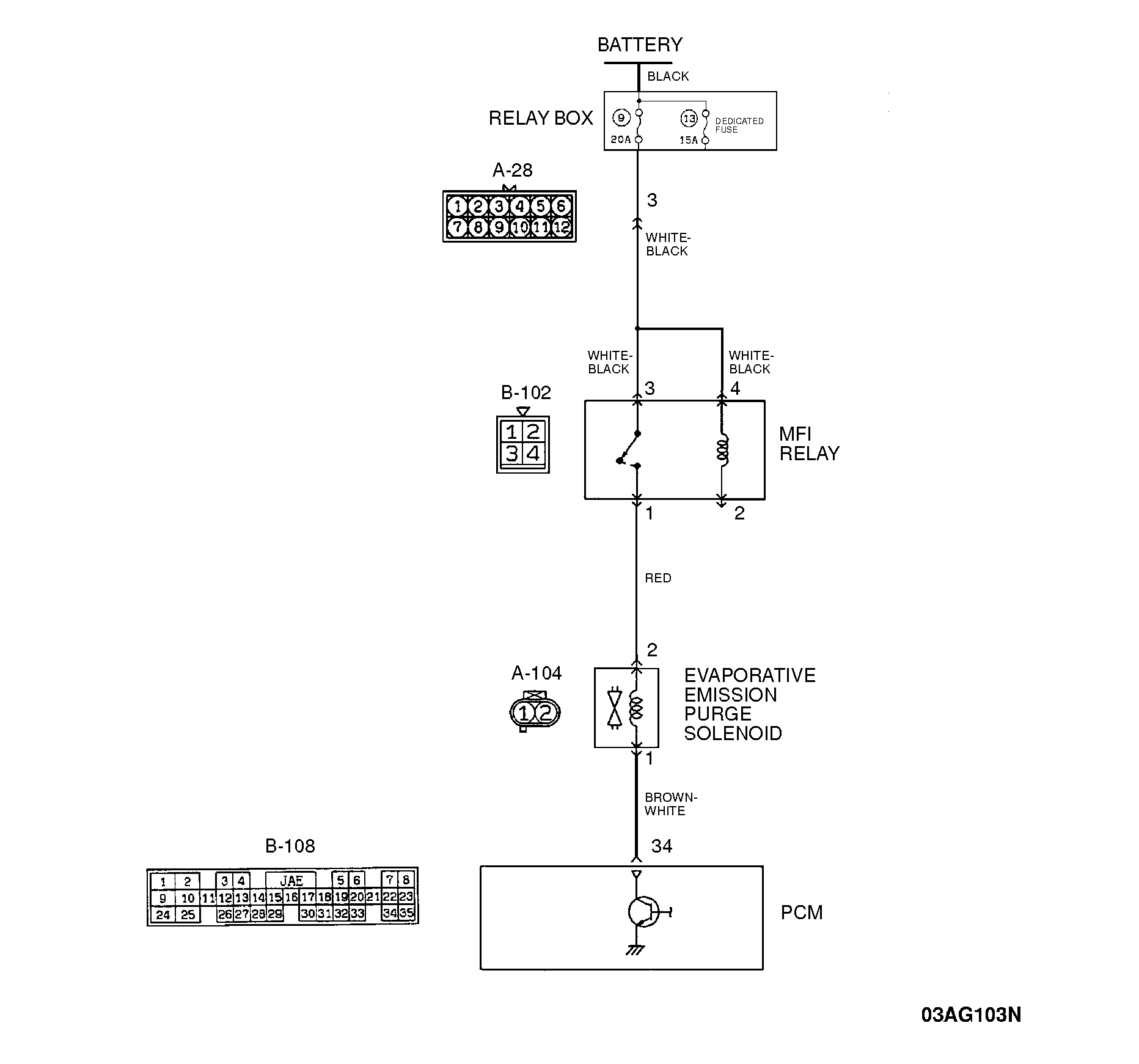
| Code No. P0443 | Evaporative Emission Control System Purge Control Valve Circuit Malfunction |
||||||||||||||||||||||||||||||||||||||||||||||||||||||||||||||||||||||||||||||
| DIAGNOSIS Required Special Tool: MB991502: Scan Tool (MUT-II) CAUTION: To prevent damage to scan tool MB991502, always turn the ignition switch to "LOCK" (OFF) position before connecting or disconnecting scan tool MB991502. If an operating sound and a vibration are not confirmed, go to Step 2. |
|||||||||||||||||||||||||||||||||||||||||||||||||||||||||||||||||||||||||||||||
| STEP 1. Using scan tool MB991502, actuator test item 08: Evaporative Emission Purge Solenoid. (1)Remove the engine cover. (2)Connect scan tool MB991502 to the data link connector. (3)Turn the ignition switch to "ON" position. (4)Set scan tool MB991502 to the actuator test mode for item 08, Evaporative Emission Purge Solenoid. •An operating sound should be heard and vibration should be felt when the evaporative emission purge solenoid is operated. If a operating sound and a vibration are confirmed, this malfunction is intermittent. Refer to GROUP 00, How to Use Troubleshooting/Inspection Service Points - How to Cope With Intermittent Malfunction. If an operating sound and a vibration are not confirmed, go to Step 2. |
|||||||||||||||||||||||||||||||||||||||||||||||||||||||||||||||||||||||||||||||
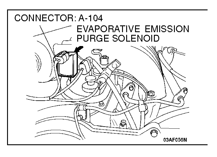
| STEP 2. Check the 12-volt supply circuit voltage at evaporative emission purge solenoid connector A-104. (1)Do not disconnect the evaporative emission purge solenoid connector A-104. (2)Turn the ignition switch to "ON" position. (3)Measure the voltage between terminal 1 and ground by backprobing. •Voltage should be battery positive voltage. (4)Turn the ignition switch to "LOCK" (OFF) position. If battery positive voltage, go to Step 3. If not battery positive voltage, go to Step 6. |
|||||||||||||||||||||||||||||||||||||||||||||||||||||||||||||||||||||||||||||||
| STEP 3. Check the 12-volt supply circuit voltage at evaporative emission purge solenoid connector A-104. (1)Do not disconnect the evaporative emission purge solenoid connector A-104. (2)Turn the ignition switch to "ON" position. (3)Measure the voltage between terminal 2 and ground by backprobing. •Voltage should be battery positive voltage. (4)Turn the ignition switch "LOCK" (OFF) position. If battery positive voltage, go to Step 4. If not battery positive voltage, go to Step 11. |
|||||||||||||||||||||||||||||||||||||||||||||||||||||||||||||||||||||||||||||||
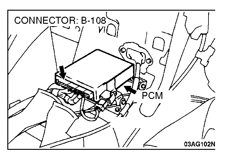
| STEP 4. Check the 12-volt supply circuit voltage at PCM connector B-108. (1)Do not disconnect PCM connector B-108. (2)Turn the ignition switch to "ON" position. (3)Measure the voltage between terminal 34 and ground by backprobing. •Voltage should be battery positive voltage. (4)Turn the ignition switch to "LOCK" (OFF) position. If battery positive voltage, go to Step 5. If not battery positive voltage, check connector A-104, B-108 and repair or replace as required. Refer to GROUP 00E, Harness Connector Inspection. If connector A-104, B-108 is in good condition, check the harness between evaporative emission purge solenoid connector A-104 and PCM connector B-108 for open circuit or damage. Then repair if necessary. Then go to Step 12. |
|||||||||||||||||||||||||||||||||||||||||||||||||||||||||||||||||||||||||||||||
| CAUTION: To prevent damage to scan tool MB991502, always turn the ignition switch to "LOCK" (OFF) position before connecting or disconnecting scan tool MB991502. STEP 5. Using scan tool MB991502, check the circuit voltage at PCM connector B-108. item 08: Evaporative Emission Purge Solenoid. (1)Connect scan tool MB991502 to the data link connector. (2)Do not disconnect PCM connector C-108. (3)Turn the ignition switch to "ON" position. (4)Measure the voltage between terminal 34 and ground by backprobing. (5)Set scan tool MB991502 to the actuator test mode for item 08, Evaporative Emission Purge Solenoid. •Voltage should be 1 volt or less.(while the solenoid valve is operating) (6)Turn the ignition switch to "LOCK" (OFF) position. If 1 volt or less, replace the evaporative emission purge solenoid. Then go to Step 12. If more than 1 volt, replace the PCM. Then go to Step 12. |
|||||||||||||||||||||||||||||||||||||||||||||||||||||||||||||||||||||||||||||||
| STEP 6. Check evaporative emission purge solenoid connector A-104 for damage. If harness connector A-104 is in good condition, go to Step 7. If harness connector A-104 is damaged, repair or replace it. Refer to GROUP 00E, Harness Connector Inspection. Then go to Step 12. |
|||||||||||||||||||||||||||||||||||||||||||||||||||||||||||||||||||||||||||||||
| STEP 7. Check the harness between evaporative emission purge solenoid connector A-104 and PCM connector B-108 for short circuit to ground. (1)Disconnect evaporative emission purge solenoid connector A-104 and measure at the harness side. (2)Check the continuity between terminal 2 and ground. •There should be open circuit. If open circuit, go to Step 8. If continuity, go to Step 10 |
|||||||||||||||||||||||||||||||||||||||||||||||||||||||||||||||||||||||||||||||
| STEP 8. Check the fuse for open circuit. If there is continuity, go to Step 9. If open circuit, check all connectors, which are located between the fuse block to the evaporative emission purge solenoid, for damage. Then repair if necessary. (Refer to GROUP 90, Circuit Diagrams) Refer to GROUP 00E, Harness Connector Inspection. If all the connectors are in good condition check the harness between the fuse block and evaporative emission purge solenoid for short circuit to ground, then repair if necessary. Then replace the defective fuse, and go to Step 12. |
|||||||||||||||||||||||||||||||||||||||||||||||||||||||||||||||||||||||||||||||
| STEP 9. Check the MFI relay. Refer to If the relay is normal, check all connectors, which are located between the battery and evaporative emission purge solenoid, for damage. Then repair if necessary. (Refer to GROUP 90, Circuit Diagrams) Refer to GROUP 00E, Harness Connector Inspection. If all the connectors are in good condition, check the harness between the battery and the evaporative emission purge solenoid for open circuit or damage. Then repair if necessary. Then go to Step 12. If the relay is defective, replace the MFI relay. Then go to Step 12. |
|||||||||||||||||||||||||||||||||||||||||||||||||||||||||||||||||||||||||||||||
| STEP 10. Check the harness between evaporative emission purge solenoid connector A-104 and PCM connector B-108 for short circuit to ground. (1)Disconnect evaporative emission purge solenoid connector A-104 and PCM connector B-108. (2)Check the continuity between evaporative emission purge solenoid connector A-104 harness side terminal 2 and the ground. •There should be open circuit. If open circuit, replace the PCM. Then go to Step 12. If there is continuity, check the harness between evaporative emission purge solenoid connector A-104 and PCM connector B-108 for short circuit to ground. Then repair if necessary. Then go to Step 12. |
|||||||||||||||||||||||||||||||||||||||||||||||||||||||||||||||||||||||||||||||
| STEP 11. Check the evaporative emission purge solenoid. (1)Disconnect connector A-104. (2)Measure the resistance between the terminals of the evaporative emission purge solenoid. Standard value: 30 - 34 Ω [at 20°C (68°F)] If within specifications, check the evaporative emission purge solenoid connector A-104 and repair or replace as required. Refer to GROUP 00E, Harness Connector Inspection. Then go to Step 12. If not within specifications, replace the evaporative emission purge solenoid. Then go to Step 12. |
|||||||||||||||||||||||||||||||||||||||||||||||||||||||||||||||||||||||||||||||
| STEP 12. Test the OBD-II drive cycle. (1)Carry out a test drive with the drive cycle pattern. Refer to (2)Read the diagnostic trouble code, and confirm that diagnostic trouble code P0443 does not reset. |
|||||||||||||||||||||||||||||||||||||||||||||||||||||||||||||||||||||||||||||||