![[Previous]](../../../BUTTONS/fprev.png)
![[Next]](../../../BUTTONS/fnext.png)
|
DTC P0451, P0452, P0453 |
Evaporative Emission Control System Pressure Sensor Malfunction |
||||||||||||||||||||||||||||||||||||||||||||||||||||||||||||||||||||||||||||||
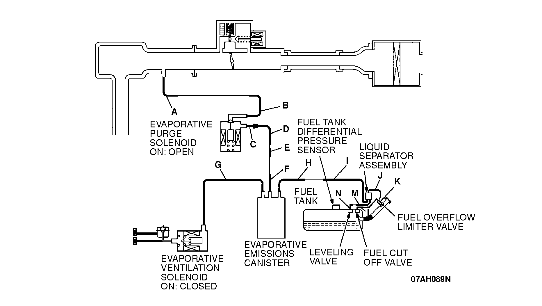
| DIAGNOSIS Required Special Tools: MB991502: Scan Tool (MUT-II) MB991658: Test Harness Set CAUTION: To prevent damage to scan tool MB991502, always turn the ignition switch to "LOCK" (OFF) position before connecting or disconnecting scan tool MB991502. STEP 1. Using scan tool MB991502, check data list item 73: Fuel Tank Differential Pressure Sensor. (1)Connect scan tool MB991502 to the data link connector. (2)Turn the ignition switch to "ON" position. (3)Remove the fuel cap. (4)Disconnect the hose G from the evaporative emission ventilation solenoid, and then plug the hose end. (5)Set scan tool MB991502 to the data reading mode for item 73, Fuel Tank Differential Pressure Sensor. ĽThe fuel tank pressures should be -1.5 to 1.5kPa. (6)Connect an evaporative emission system pressure pump to the fuel filler neck, and apply pressure. ĽThe scan tool reading should increase. If within specifications, go to Step 16. If not within specifications, go to Step 2. |
|||||||||||||||||||||||||||||||||||||||||||||||||||||||||||||||||||||||||||||||
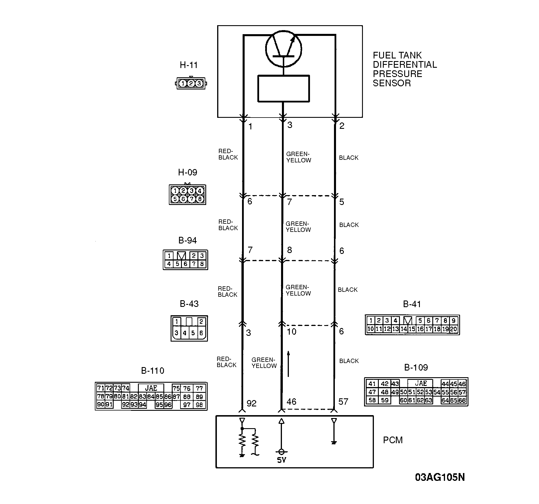
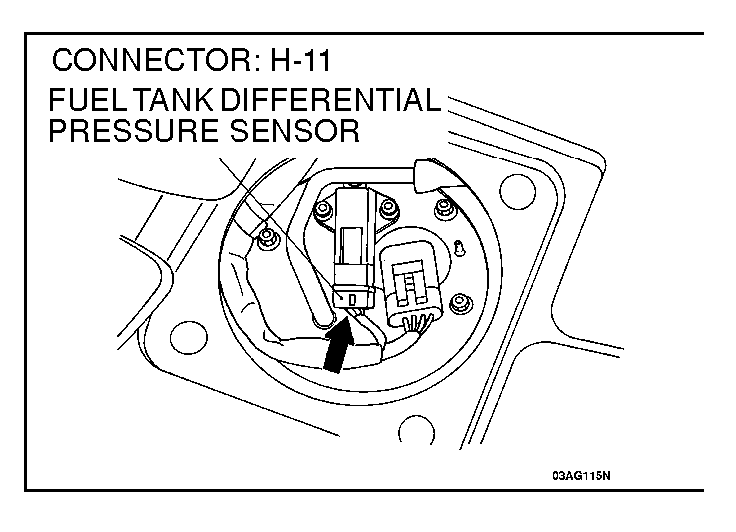
| STEP 2. Check the output circuit voltage at fuel tank differential pressure connector H-11. (1)Remove the rear seat cushion. (2)Remove the protector. (3)Remove the pressure sensor without disconnecting the differential pressure connector H-11. (4)Turn the ignition switch to "ON" position. (5)Remove the fuel cap. (6)Measure the voltage between terminal 1 and ground by backprobing. ĽVoltage should be between 2.0 and 3.0 volts. (7)Turn the ignition switch to "LOCK" (OFF) position. If within specifications, go to Step 7. If not within specifications, go to Step 3. |
|||||||||||||||||||||||||||||||||||||||||||||||||||||||||||||||||||||||||||||||
| STEP 3. Check the 5-volt supply circuit voltage at fuel tank differential pressure sensor connector H-11. (1)Do not disconnect fuel tank differential pressure sensor connector H-11. (2)Turn the ignition switch to "ON" position. (3)Measure the voltage between terminal 3 and ground by backprobing. ĽVoltage should be between 4.8 and 5.2 volts. (4)Turn the ignition switch to "LOCK" (OFF) position. If within specifications, go to Step 4. If not within specifications, go to Step 8. |
|||||||||||||||||||||||||||||||||||||||||||||||||||||||||||||||||||||||||||||||
| STEP 4. Check the ground circuit voltage at fuel tank differential pressure sensor connector H-11. (1)Do not disconnect fuel tank differential pressure sensor connector H-11. (2)Turn the ignition switch to "ON" position. (3)Measure the voltage between terminal 2 and ground by backprobing. ĽVoltage should be 0.5 volt or less. (4)Turn the ignition switch to "LOCK" (OFF) position. If 0.5 volt or less, go to Step 5. If more than 0.5 volt, go to Step 12. |
|||||||||||||||||||||||||||||||||||||||||||||||||||||||||||||||||||||||||||||||
| STEP 5. Check fuel tank differential pressure sensor connector H-11 for damage. If fuel tank differential pressure sensor connector H-11 is in good condition, go to Step 6. If fuel tank differential pressure sensor connector H-11 is damaged, repair or replace it. Refer to GROUP 00E, Harness Connector Inspection. Then go to Step 23. |
|||||||||||||||||||||||||||||||||||||||||||||||||||||||||||||||||||||||||||||||
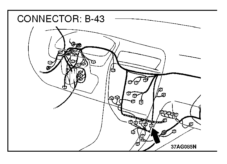
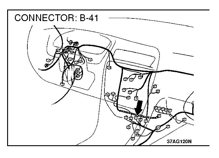
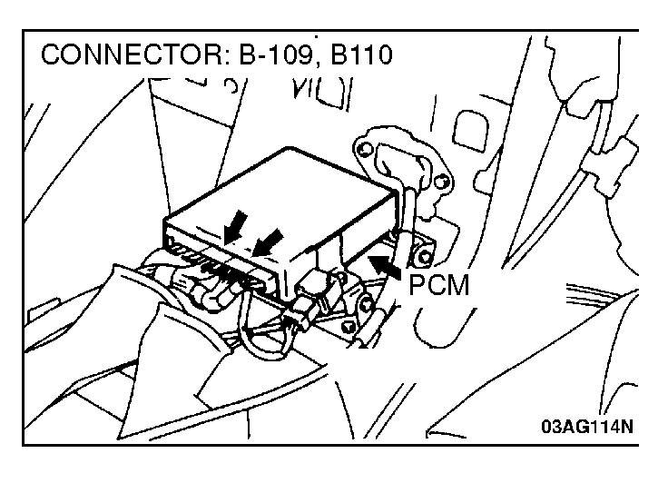
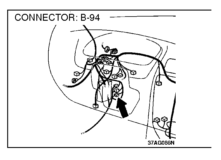
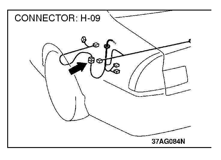
| STEP 6. Check the output voltage at fuel tank differential pressure sensor connector H-11. (1)Disconnect the fuel tank differential pressure sensor connector H-11. (2)Use special tool (MB991658) to connect terminals 2 and 3 of the harness side connector to those of the sensor side connector, respectively. (3)Turn the ignition switch to "ON" position. (4)Remove the fuel cap. (5)Measure the voltage between sensor side connector terminal 1 and ground. ĽVoltage should be between 2.0 and 3.0 volts. (6)Turn the ignition switch to "LOCK" (OFF) position. If within specifications, check connectors H-09, B-94, B-41, B-43, B-110 and repair or replace as required. Refer to GROUP 00E, Harness Connector Inspection. If connectors H-09, B-94, B-41, B-43, B-110 are in good condition, check the harness between fuel tank pressure sensor connector H-11 and PCM connector B-109 for short circuit to ground, and then repair if necessary. Then go to Step 23. If not within specifications, replace the fuel tank differential pressure sensor. Then go to Step 23. |
|||||||||||||||||||||||||||||||||||||||||||||||||||||||||||||||||||||||||||||||
| STEP 7. Check the output circuit voltage at PCM connector B-110. (1)Do not disconnect the PCM connector B-110. (2)Turn the ignition switch to "ON" position. (3)Remove the fuel cap. (4)Measure the voltage between terminal 92 and ground by backprobing. ĽVoltage should be between 2.0 and 3.0 volt. (5)Turn the ignition switch to "LOCK" (OFF) position. If within specifications, go to Step 14. If not within specifications, check connectors H-11, H-09, B-94, B-41, B-43, B-110 and repair or replace as required. Refer to GROUP 00E, Harness Connector Inspection. If connectors H-11, H-09, B-94, B-41, B-43, B-110 are in good condition, check the harness between intermediate connector H-11 and PCM connector B-109 for open circuit or damage. Then repair if necessary. Then go to Step 23. |
|||||||||||||||||||||||||||||||||||||||||||||||||||||||||||||||||||||||||||||||
| STEP 8. Check the 5-volt supply circuit voltage at PCM connector B-109. (1)Do not disconnect PCM connector B-109. (2)Turn the ignition switch to "ON" position. (3)Measure the voltage between terminal 46 and ground by backprobing. ĽVoltage should be between 4.8 and 5.2 volts. (4)Turn the ignition switch to "LOCK" (OFF) position. If within specifications, check connectors H-11, H-09, B-94, B-41, B-43, B-109 and repair or replace as required. Refer to GROUP 00E, Harness Connector Inspection. If connectors H-11, H-09, B-94, B-41, B-43, B-109 are in good condition, check the harness between intermediate connector H-11 and PCM connector B-109 for open circuit or damage. Then repair if necessary. Then go to Step 23. If not within specifications, go to Step 9. |
|||||||||||||||||||||||||||||||||||||||||||||||||||||||||||||||||||||||||||||||
| STEP 9. Check PCM connector B-109 for damage. If connector B-109 is in good condition, go to Step 10. If connector B-109 is damaged, repair or replace it. Refer to GROUP 00E, Harness Connector Inspection. Then go to Step 23. |
|||||||||||||||||||||||||||||||||||||||||||||||||||||||||||||||||||||||||||||||
| STEP 10. Check the sensor power supply line for short circuit to ground at PCM connector B-109. (1)Disconnect PCM connector B-109 and measure at the harness side. (2)Check for the continuity between terminal 46 and ground. ĽThere should be 2 ohms or more. If 2 ohms or more, replace PCM. Then go to Step 23. If less than 2 ohms, go to Step 11. |
|||||||||||||||||||||||||||||||||||||||||||||||||||||||||||||||||||||||||||||||
| STEP 11. Check the sensor power supply lines. Check all the sensor power supply lines, which flow through the harness PCM connector (terminal 46) and then repair if necessary. (Refer to GROUP 90, Circuit Diagrams). Then go to Step 25. |
|||||||||||||||||||||||||||||||||||||||||||||||||||||||||||||||||||||||||||||||
| STEP 12. Check the ground circuit voltage at PCM connector B-109. (1)Do not disconnect PCM connector B-109. (2)Turn the ignition switch to "ON" position. (3)Measure the voltage between terminal 57 and ground by backprobing. ĽVoltage should be 0.5 volt or less. (4)Turn the ignition switch to "LOCK" (OFF) position. If 0.5 volt or less, check connectors H-11, H-09, B-94, B-41, B-43, B-109 and repair or replace as required. Refer to GROUP 00E, Harness Connector Inspection. If connectors H-11, H-09, B-94, B-41, B-43, B-109 are in good condition, check the harness between intermediate connector H-11 and PCM connector B-109 for open circuit or damage, and then repair if necessary. Then go to Step 23. If more than 0.5 volt, go to Step 13. |
|||||||||||||||||||||||||||||||||||||||||||||||||||||||||||||||||||||||||||||||
| STEP 13. Check PCM connector B-109 for damage. If connector B-109 is in good condition, replace the PCM. Then go to Step 25. If connector B-109 is damaged, repair or replace it. Refer to GROUP 00E, Harness Connector Inspection. Then go to Step 23. |
|||||||||||||||||||||||||||||||||||||||||||||||||||||||||||||||||||||||||||||||
| STEP 14. Check PCM connector B-110 for damage. If connector B-110 is in good condition, go to Step 15. If connector B-110 is damaged, repair or replace it. Refer to GROUP 00E, Harness Connector Inspection. Then go to step 23. |
|||||||||||||||||||||||||||||||||||||||||||||||||||||||||||||||||||||||||||||||
| CAUTION: To prevent damage to scan tool MB991502, always turn the ignition switch to "LOCK" (OFF) position before connecting or disconnecting scan tool MB991502. STEP 15. Using scan tool MB991502, check data list item 73: Fuel Tank Differential Pressure Sensor. (1)Connect scan tool MB991502 to the data link connector. (2)Turn the ignition switch to "ON" position. (3)Remove the fuel cap. (4)Disconnect the hose G from the evaporative emission ventilation solenoid, and then plug the hose end. (5)Set scan tool MB991502 to the data reading mode for item 73, Fuel Tank Differential Pressure Sensor. ĽThe fuel tank pressure should be -1.5 to 1.5kPa. (6)Connect an evaporative emission system pressure pump to the fuel filler neck, and apply pressure. ĽThe scan tool reading should increase. If within specifications, go to Step 23. If not within specifications, replace the PCM. Then go to Step 23. |
|||||||||||||||||||||||||||||||||||||||||||||||||||||||||||||||||||||||||||||||
| STEP 16. Check the fuel overflow limiter valve plunger and flapper door operation. NOTE: The fuel overflow limiter valve plunger opens and closes in sequence with the flapper door and fuel overflow limiter valve plunger. When the fuel gun is inserted in the fuel filler neck and the flapper door is opened, the fuel overflow limiter valve plunger will close. (The fuel overflow limiter valve plunger will move to the top of the neck.) When the fuel cap is closed, the fuel cap pushes the fuel overflow limiter valve plunger and the fuel overflow limiter valve plunger opens. If the flapper door or fuel overflow limiter valve plunger does not operate correctly, the fuel overflow limiter valve plunger will remain closed even if the fuel cap is closed (same state as when the evaporator line is clogged). This can cause DTC P0450 to occur. |
|||||||||||||||||||||||||||||||||||||||||||||||||||||||||||||||||||||||||||||||
| (1)Remove the fuel cap. (2)Push the flapper with an ornament remover, etc., to activate the valve. NOTE: The fuel overflow limiter valve plunger moves upward when the flapper is pushed. (3)Tighten the fuel cap until three clicks are heard. |
|||||||||||||||||||||||||||||||||||||||||||||||||||||||||||||||||||||||||||||||
| (4)Remove the fuel cap again, and with the fuel overflow limiter valve plunger pushed in, measure the projection amount. (5)Confirm that the distance from the end of the fuel tank filler neck to the end of the fuel overflow limiter valve plunger is 28 mm (1.1 inches) or more. If the fuel overflow limiter valve plunger does not return completely [when less than 28mm (1.1 inches)], replace the fuel tank filler neck, completely tighten the fuel cap and go to Step 23. If the fuel overflow limiter valve plunger has completely returned [when 28 mm (1.1 inches) or more], completely tighten the fuel cap and go to Step 17. |
|||||||||||||||||||||||||||||||||||||||||||||||||||||||||||||||||||||||||||||||
| STEP 17. Check for clogging in the evaporator line from hose F to H and from M to N. (1)Install the EVAP pressure pump outlet hose to the fuel tank filler neck as described in the pump manufacturer's instructions. (2)On the EVAP pressure pump, set the pressure/hold valve to OPEN, and set the vent valve to CLOSED. Turn the pump timer to ON. You can reset the timer as required. (These settings are listed under "Leak Test" in the pump instructions.) |
|||||||||||||||||||||||||||||||||||||||||||||||||||||||||||||||||||||||||||||||
| (3)Air should pass through the air filter. If the air passes, go to Step 23. If the air does not pass, go to Step 18. |
|||||||||||||||||||||||||||||||||||||||||||||||||||||||||||||||||||||||||||||||
| STEP 18. Check for clogging air filter. Check the air filter for clogging. If the air filter is clogged, replace the air filter. Then go to Step 23. If the air filter is not clogged, go to Step 20. |
|||||||||||||||||||||||||||||||||||||||||||||||||||||||||||||||||||||||||||||||
| STEP 19. Check for clogging in the evaporator line hoses G to K. Perform clogging test with a hand vacuum pump on each hose G to K. If the clogging section is pinpointed, replace that hose, and go to Step 23. If the location of the leak cannot be pinpointed, go to Step 20. |
|||||||||||||||||||||||||||||||||||||||||||||||||||||||||||||||||||||||||||||||
| STEP 20. Check for clogging in the evaporative emission canister. (1)Connect a hand vacuum pump to the vent nipple of the evaporative emission canister. (2)Plug the other two nipples or loop a hose between the other nipples. (3)Apply vacuum. When each nipple is unplugged, the vacuum should fluctuate. If the applied vacuum fluctuates, go to Step 23. If the vacuum does not fluctuate, replace the evaporative emission canister and go to Step 23. |
|||||||||||||||||||||||||||||||||||||||||||||||||||||||||||||||||||||||||||||||
| STEP 21. Check the evaporative emission ventilation solenoid using the scan tool MB991502. (Actuator test item 29) (1)Lower the evaporative emission canister assembly, turn the ignition switch to "ON" position, and disconnect hose G from the evaporative emission ventilation solenoid side. (2)Connect the hand vacuum pump to the nipple of the evaporative emission ventilation solenoid from which the hose has been disconnected. (3)Drive the evaporative emission ventilation solenoid with the scan tool MB991502 actuator test and confirm that the vacuum does not fluctuate when the vacuum is applied with the hand vacuum pump. If the evaporative emission ventilation solenoid operates correctly and the applied vacuum does not fluctuate, go to Step 22. If the evaporative emission ventilation solenoid operates correctly, but the vacuum is not maintained, replace the evaporative emission ventilation solenoid, and then go to Step 23. If the evaporative emission ventilation solenoid does not operate, refer to the evaporative emission ventilation solenoid trouble code DTC P0446. STEP 22. Check for clogging in the evaporator line from hoses L and N. (1)Remove the fuel tank. (Refer to GROUP 13F, Fuel Tank) (2)Carry out the clogging test with a hand vacuum pump on each hose L and N. If the location of the leak or clog is pinpointed, replace that hose and reinstall the fuel tank, go to Step 23. If the location of the leak or clog cannot be pinpointed, install the fuel tank and go to Step 23. STEP 23. Test the OBD-II drive cycle. (1)Carry out a test drive with the drive cycle pattern. Refer to (2)Read the diagnostic trouble codes, and confirm that diagnostic trouble codes P0451, P0452, P0453 do not reset. |
|||||||||||||||||||||||||||||||||||||||||||||||||||||||||||||||||||||||||||||||