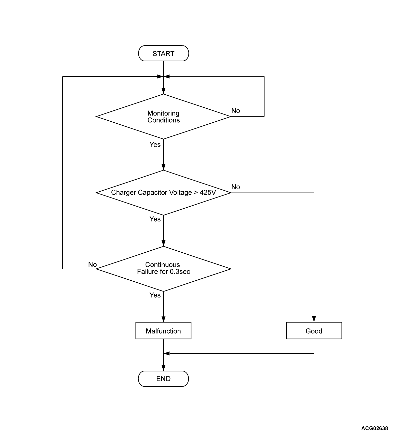
DTC P1D19: PFC Circuit Output Voltage Abnormal (High Voltage)
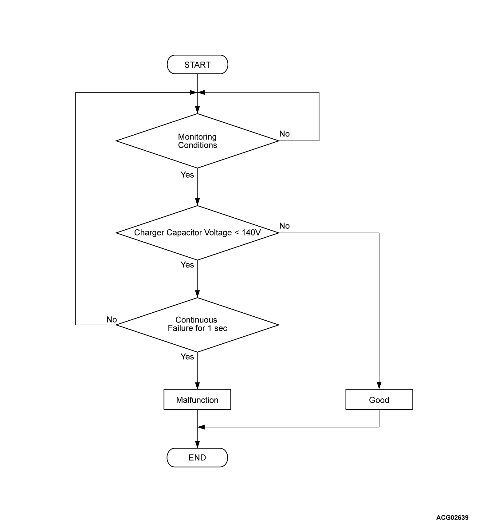
DTC P1D20: PFC Circuit Output Voltage Abnormal (Low Voltage)
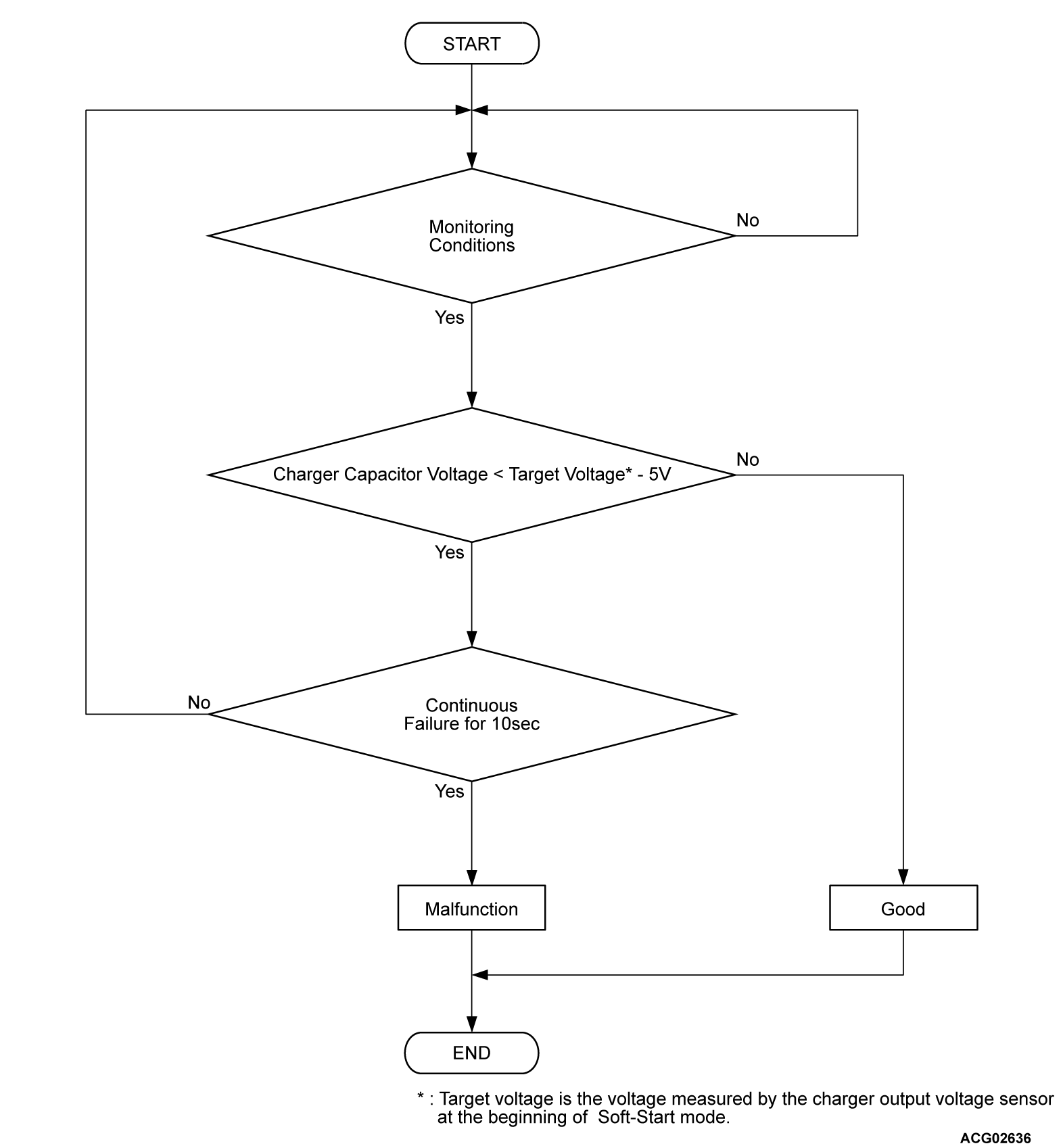
DTC P1D21: PFC Circuit Output Voltage Abnormal (Control Fail)
DTC P1D20: PFC Circuit Output Voltage Abnormal (Low Voltage)
DTC P1D21: PFC Circuit Output Voltage Abnormal (Control Fail)
DESCRIPTIONS OF MONITOR METHODS <DTC P1D21>
- On-board charger (OBC) capacitor voltage increases at the beginning of each charge cycle.
- On-board charger (OBC) capacitor voltage is monitored in the following sequential stages.
- From the capacitor voltage (V1) until the capacitor voltage increases to V2.
note - V1: 120 volts (100 volts input) or 240 volts (200 volts input)
- V2: Voltage measured by charger output voltage sensor when the charger capacitor voltage reaches V1.
MONITOR EXECUTION
- Continuous
MONITOR EXECUTION CONDITIONS (Other monitor and Sensor)
Other Monitor (There is no temporary DTC set in memory for the item monitored below)
- Battery charger control module (OBC) monitor
Sensor (The sensor below is determined to be normal)
- Not applicable
DTC SET CONDITIONS
Check Conditions <DTC P0D19>
- OBC power supply voltage is 10 volts to 16 volts.
Judgment Criterion <DTC P0D19>
- Change of the charger capacitor voltage is more than 425 volts for 0.3 second.
Check Conditions <DTC P1D20>
- Charge permission from PHEV-ECU is on.
- Charger capacitor voltage is more than target voltage.
note Target voltage is the voltage measured by the charger output voltage sensor at the beginning of soft-start mode.
Judgment Criterion <DTC P1D20>
- Change of the charger capacitor voltage is less than 140 volts for 1 second.
Check Conditions <DTC P1D21>
- Charge permission from PHEV-ECU is on.
- Charger capacitor voltage is 240 volts (200 volts input) or 120 volts (100 voltage input) to target voltage.
note Target voltage is the voltage measured by the charger output voltage sensor at the beginning of soft-start mode.
Judgment Criterion <DTC P1D21>
- When charger capacitor voltage remains within the value obtained by subtracting 5 volts from the target voltage for 10 seconds
note Target voltage is the voltage measured by the charger output voltage sensor at the beginning of soft-start mode.
OBD-II DRIVE CYCLE PATTERN
FAIL-SAFE AND BACKUP FUNCTION
- The charge is stopped.
PROBABLE CAUSE
- The on board charger/DC-DC converter is failed.
![[Previous]](../../../buttons/fprev.png)
![[Next]](../../../buttons/fnext.png)


