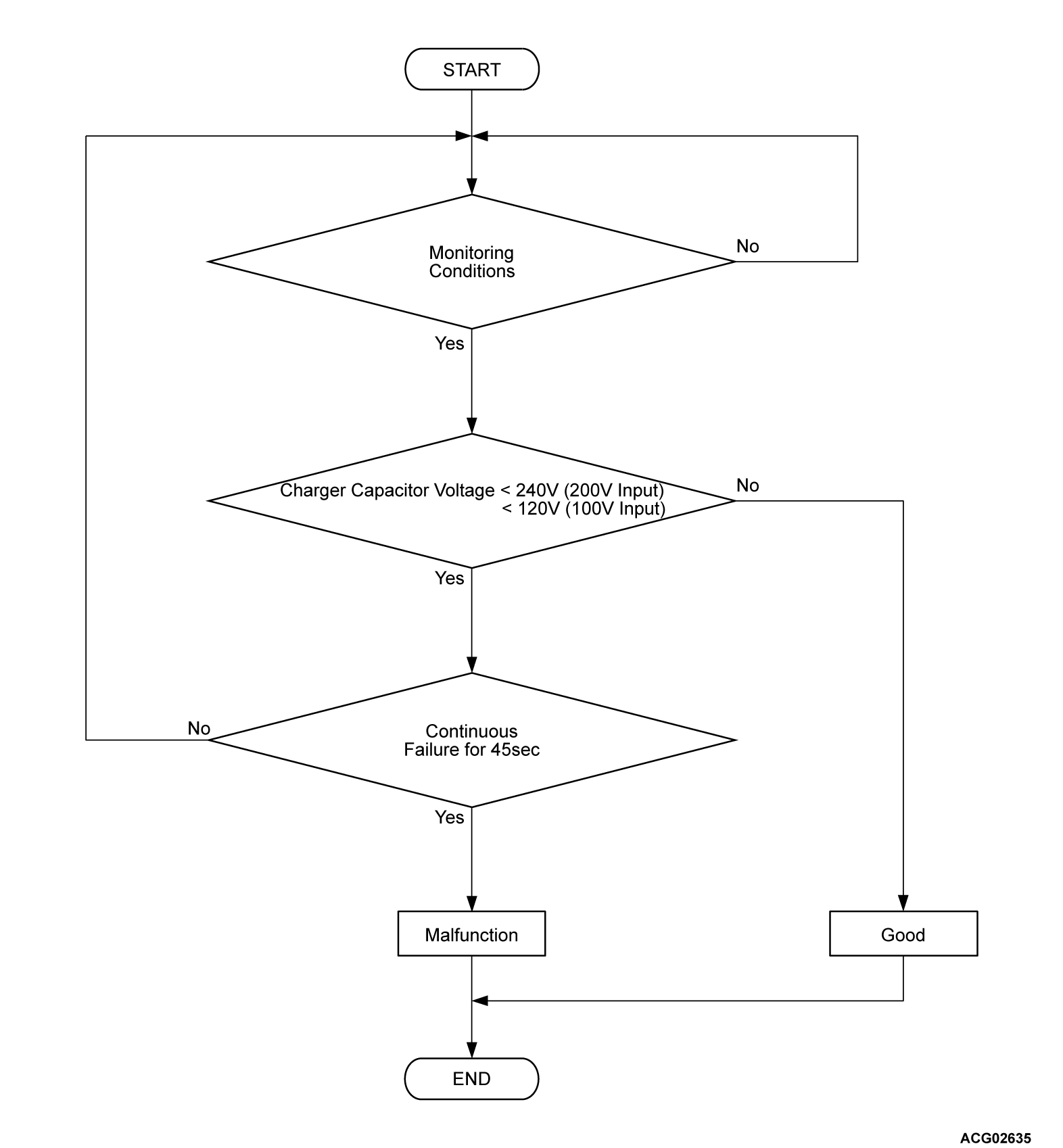
DTC P0D26: BATT. Charger System (Precharge)
DESCRIPTIONS OF MONITOR METHODS
- On-board charger (OBC) capacitor voltage increases at the beginning of each charge cycle.
- On-board charger (OBC) capacitor voltage is monitored in the following sequential stages.
- From charge permission is received by OBC until the capacitor voltage increases to V1.
note V1: 120 volts (100 volts input) or 240 volts (200 volts input)
MONITOR EXECUTION
- Continuous
MONITOR EXECUTION CONDITIONS (Other monitor and Sensor)
Other Monitor (There is no temporary DTC set in memory for the item monitored below)
- Battery charger control module (OBC) monitor
Sensor (The sensor below is determined to be normal)
- Not applicable
DTC SET CONDITIONS
Check Conditions
- Charge permission from PHEV-ECU is on.
- Charger voltage command value is more than 0 volt.
- Input voltage is 80 volts to 120 volts.
Judgment Criterion
- Change of the charger capacitor voltage is less than 240 volts (200 volts input) or 120 volts (100 volts input) for 45 seconds.
FAIL-SAFE AND BACKUP FUNCTION
- The charge is stopped.
PROBABLE CAUSE
- The on board charger/DC-DC converter is failed.
DIAGNOSIS
STEP 1. Test the OBD-II drive cycle.
(2) Check the DTC.
Is the DTC set?
![[Previous]](../../../buttons/fprev.png)
![[Next]](../../../buttons/fnext.png)


