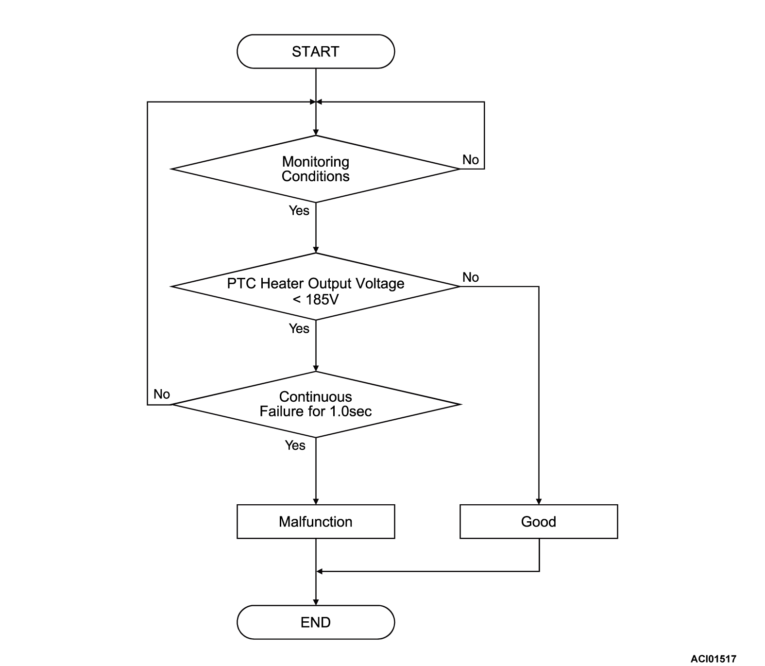
DTC P1EFA: PTC Heater Contactor Stuck OFF
| caution | Before replacing the ECU, ensure that the communication circuit is normal. |
MONITOR EXECUTION
- Continuous
MONITOR EXECUTION CONDITIONS (Other monitor and Sensor)
Other Monitor (There is no DTC set in memory for the item monitored below)
- Not applicable
Sensor (The sensor below is determined to be normal)
- Not applicable
DTC SET CONDITIONS
Check Conditions
- Battery management unit (BMU) power supply voltage is 8 volts to 16 volts.
- Time after above conditions satisfy is more than 1 seconds.
- PTC heater contactor (P) drive relay ON.
- PTC heater contactor (N) drive relay ON.
- Main drive lithium-ion battery PTC heater main relay ON continues 0.2 second.
Judgment Criterion
- The state of the PTC heater output voltage is less than 185 volts continues for 1 second.
FAIL-SAFE AND BACKUP FUNCTION
- Not available
PROBABLE CAUSES
- The high voltage fuse is failed.
- Open or short to ground system of main drive lithium-ion battery PTC heater contactor drive relay (P) or (N) circuit; poor contact of connector.
- The main drive lithium-ion battery PTC heater contactor (P) or (N) is failed
- The high-voltage cable is failed.
- The main drive lithium-ion battery PTC heater is failed.
- The battery management unit (BMU) is failed.
DIAGNOSIS
Required Special Tools
- MB991658: Test harness
STEP 1. Check of the high voltage fuse No.7 inside the main drive lithium-ion battery.
STEP 2. Measure the resistance at main drive lithium-ion battery connector.
(1) Disconnect the D-33 main drive lithium-ion battery connector, and measure at the wiring harness side.
(2) Check the resistance between the D-33 main drive lithium-ion battery connector (terminal No.3) and body ground.
OK: Continuity (2 Ω or less)
Is the check result normal?
 Repair the connector(s) or wiring harness.
STEP 3. Check the resistance at the coil of the main drive lithium-ion battery PTC heater contactor. <On-vehicles>
STEP 4. Check the main drive lithium-ion battery PTC heater contactor (P) or (N)
Is the check result normal?
STEP 5. Measure the resistance between the main drive lithium-ion battery PTC heater contactor (P) or (N) connector and the main drive lithium-ion battery connector.
(1) Disconnect the main drive lithium-ion battery PTC heater contactor (P) or (N) connector, and measure at the wiring harness side.
(2) Check the resistance between the main drive lithium-ion battery PTC heater contactor (P) connector (terminal No.1) and D-34 main drive lithium-ion battery connector (terminal No.2).
OK: Continuity (2 Ω or less)
(3) Check the resistance between the main drive lithium-ion battery PTC heater contactor (P) connector (terminal No.3) and D-33 main drive lithium-ion battery connector (terminal No.3).
OK: Continuity (2 Ω or less)
(4) Check the resistance between the main drive lithium-ion battery PTC heater contactor (N) connector (terminal No.4) and D-33 main drive lithium-ion battery connector (terminal No.3).
OK: Continuity (2 Ω or less)
(5) Check the resistance between the main drive lithium-ion battery PTC heater contactor (N) connector (terminal No.2) and D-34 main drive lithium-ion battery connector (terminal No.1, No.7).
OK: Continuity (2 Ω or less)
Is the check result normal?
STEP 6. Check the high-voltage cable.
| danger |
|
(1) Check the connecting conditions of the high-voltage cable below.
- Between the J-04 front JFB (P) terminal and J-01 rear JFB (P) terminal.
- Between the J-03 front JFB (N) terminal and J-02 rear JFB (N) terminal.
- Between the J-06 main drive lithium-ion battery PTC heater PTC heater contactor (P) terminal and J-09 main drive lithium-ion battery PTC heater PTC heater (P) terminal.
- Between the J-07 main drive lithium-ion battery PTC heater PTC heater contactor (N) terminal and J-08 main drive lithium-ion battery PTC heater PTC heater (N) terminal.
Is the check result normal?
STEP 7. Using scan tool (M.U.T.-IIISE), check whether the DTC is set again.
Recheck if the DTC is set.
(1) Erase the DTC.
(2) Depress the brake pedal, and turn on the power supply mode of the electric motor switch (READY operation)*.
| note | *: When a DTC is set, you cannot make the READY (ready to drive) indicator illuminate by making the READY operation. |
(3) Check if the DTC is set.
Is the DTC set?
STEP 8. Using scan tool (M.U.T.-IIISE), check the data list <BMU>
Check the BMU's data list (Refer to  ).
).
 ).
).- Item No.438: BAT. heat initial judge. end flag
Is the value of data list "ON"?
STEP 9. Using scan tool (M.U.T.-IIISE), check whether the DTC is set again.
(1) Depress the brake pedal, and turn on the power supply mode of the electric motor switch (READY operation)*.
| note | *: When a DTC is set, you cannot make the READY (ready to drive) indicator illuminate by making the READY operation. |
(2) Select "BMU" from system select screen of the scan tool (M.U.T.-IIISE).
(3) Select the "Special Function" from the BMU screen.
(4) Select the "Test" from the Special Function screen
(5) Select the "Battery heating system drive" from the Test screen.
| note | "Battery heating system drive" can be performed only once after the power supply mode of the electric motor switch is turned ON. |
(6) Turn off the power supply mode of the electric motor switch.
(7) Check the DTC.
Is the DTC set?
![[Previous]](../../../buttons/fprev.png)
![[Next]](../../../buttons/fnext.png)

