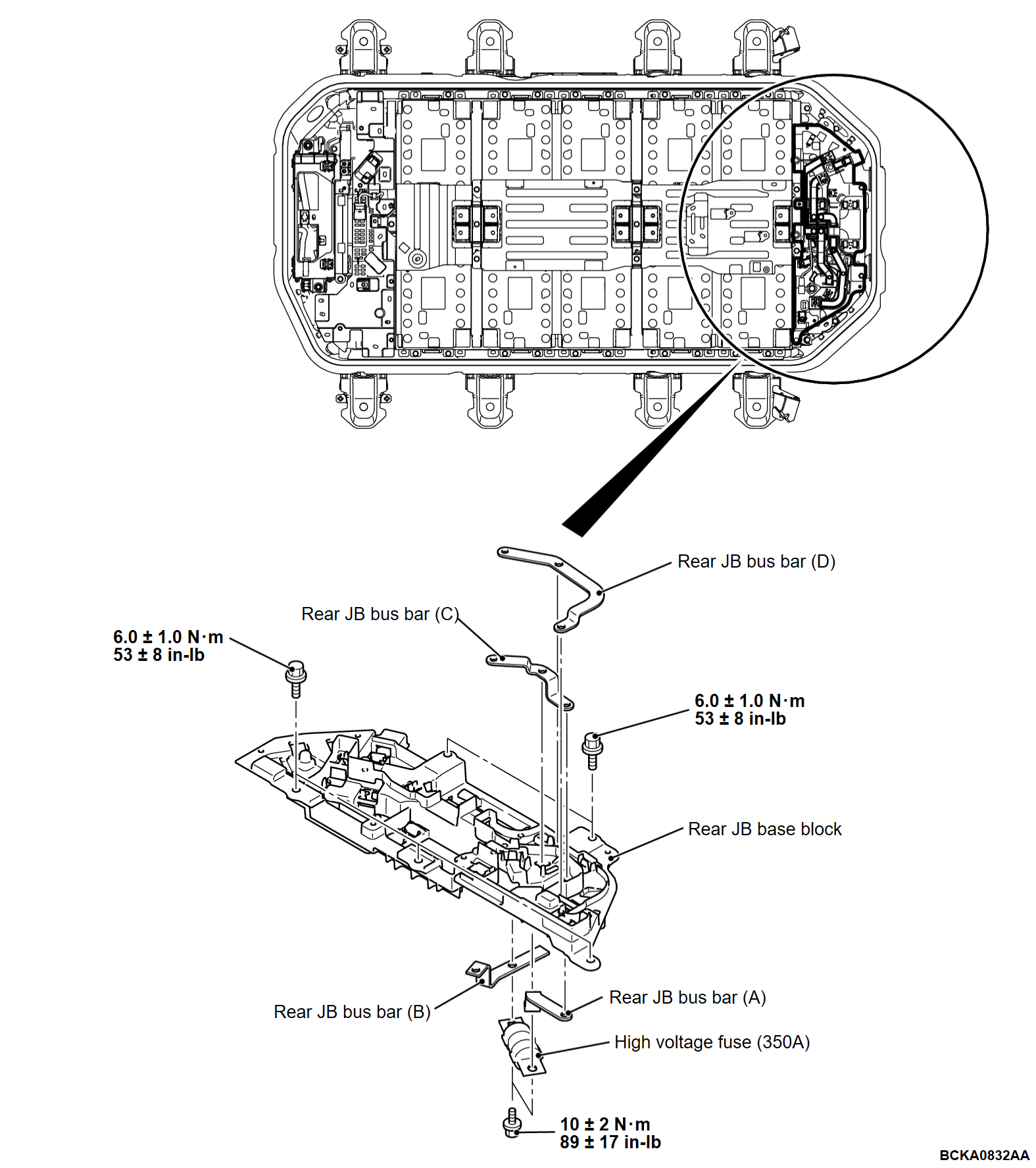
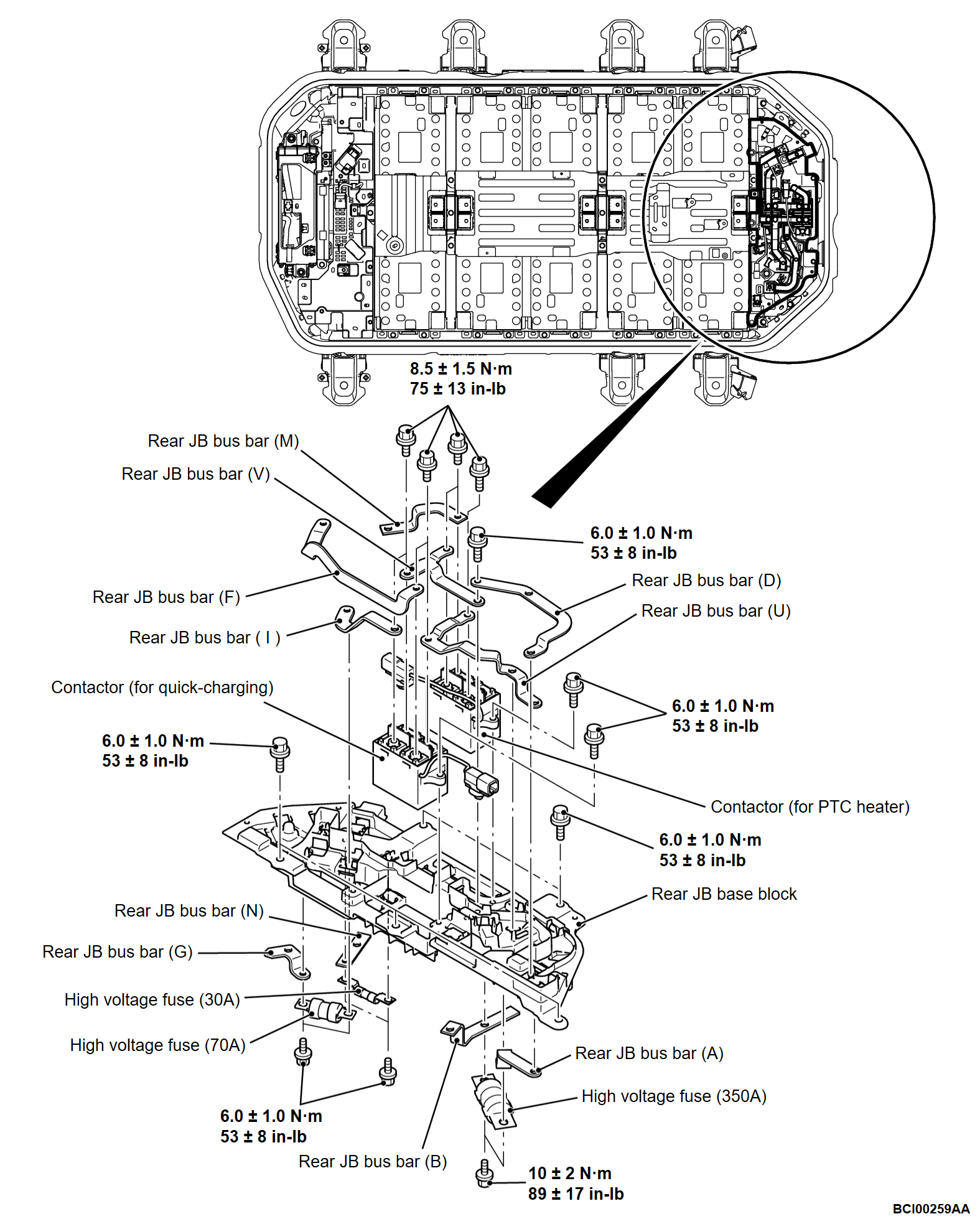
13. Rear JB assembly, rear JB bus bars (A, B, C, D, F, G, I, M, N, U and V), contactor and fuse removal and installation
Rear JB assembly, rear JB bus bars (A, B, C, D, F, G, I, M, N, U and V), contactor and fuse removal
1. Remove the bolts as shown to remove the high-voltage fuse.
2. Remove the bolts as shown to remove the rear JB assembly.
3. Remove the bolts as shown to remove the rear JB bus bars (A, B, C, D, F, G, I, M, N, U and V).
4. Remove the bolts as shown to remove the contactor.
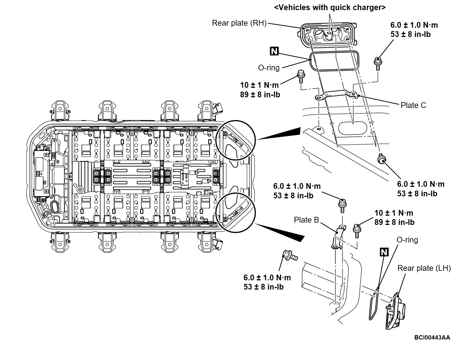
Rear plate removal
1. Remove the bolts as shown to remove the plate B and rear plate (LH).
2. Remove the O-ring.
3. Remove the bolts as shown to remove the plate C and rear plate (RH). <Vehicles with quick charger>
4. Remove the O-ring. <Vehicles with quick charger>
Rear plate installation
1. Install the O-ring. <Vehicles with quick charger>
2. Install the plate C, rear plate (RH) and tighten the bolts as shown to the specified torque. <Vehicles with quick charger>
3. Install the O-ring.
4. Install the plate B, rear plate (LH) and tighten the bolts as shown to the specified torque.
Rear JB assembly, rear JB bus bars (A, B, C, D, F, G, I, M, N, U and V), contactor and fuse installation
1. Install the contactor and tighten the bolts as shown to the specified torque.
2. Install the JB bus bars (A, B, C, D, F, G, I, M, N, U and V), and tighten the bolts as shown to the specified torque.
3. Install the rear JB assembly and tighten the bolts as shown to the specified torque.
4. Install the fuse and tighten the bolts as shown to the specified torque.
![[Previous]](../../../buttons/fprev.png)
![[Next]](../../../buttons/fnext.png)


