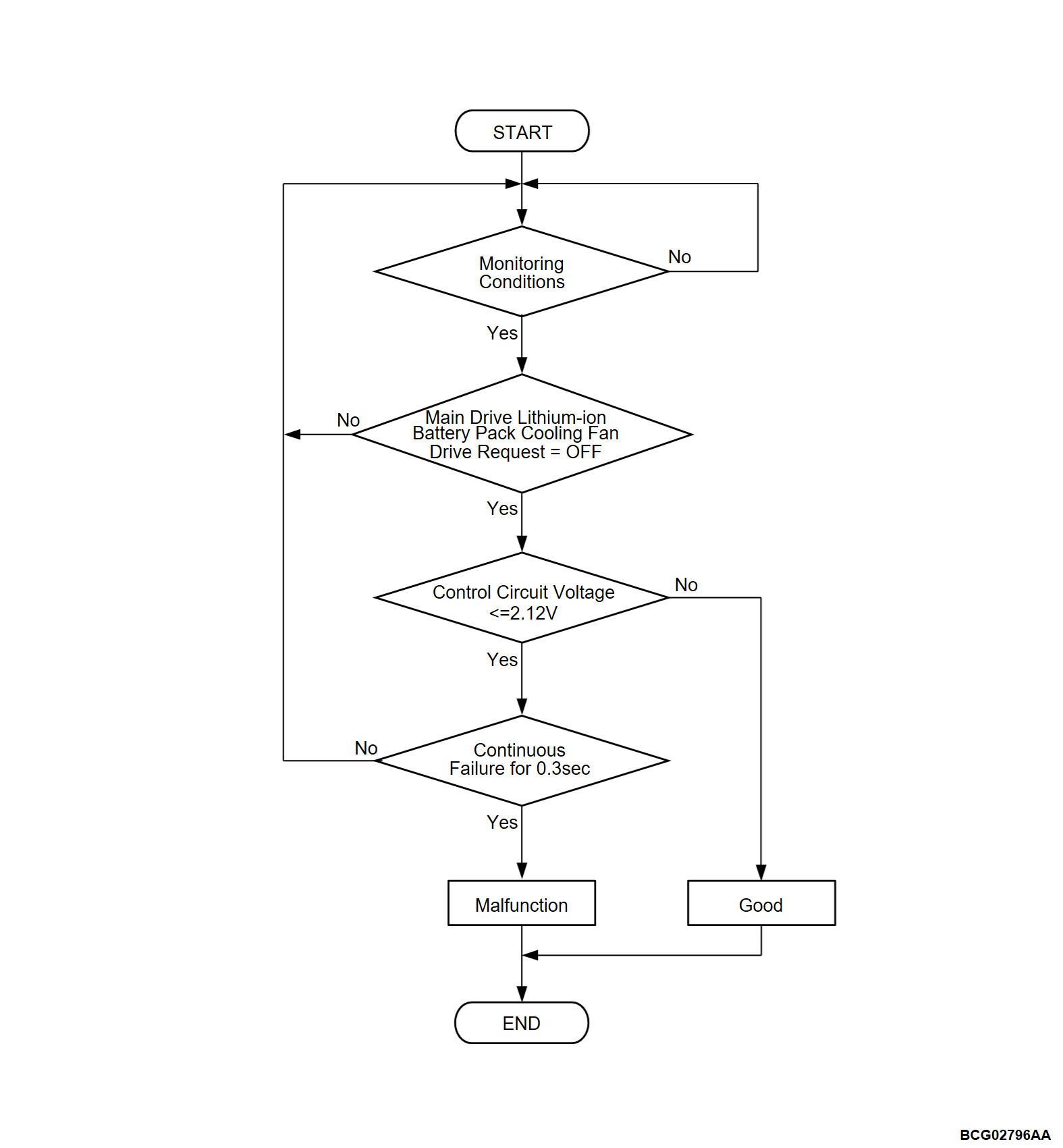
DTC P0A84: Battery Cooling Fan CONT. Circuit
| caution | Before replacing the ECU, ensure that the communication circuit is normal. |
MONITOR EXECUTION
- Continuous
MONITOR EXECUTION CONDITIONS (Other monitor and Sensor)
Other Monitor (There is no temporary DTC set in memory for the item monitored below)
- Battery CAN monitor
Sensor (The sensor below is determined to be normal)
- Not applicable
DTC SET CONDITIONS
Check Conditions
- battery management unit (BMU) power supply voltage is 8 volts to 16 volts.
- Time after above conditions satisfy is more than 1 second.
- Main drive lithium-ion battery cooling fan drive request is off (Stop command).
- Main drive lithium-ion battery PTC heater main relay ON continues 0.2 second.
Judgment Criterion
- Change of the control circuit voltage is less than 2.12 voltages for 0.3 second.
FAIL-SAFE AND BACKUP FUNCTION
- Not available
PROBABLE CAUSES
- The main drive lithium-ion battery PTC heater main relay is failed.
- The main drive lithium-ion battery cooling fan is failed.
- Short circuits to ground, power supply system of main drive lithium-ion battery cooling fan circuit; poor contact of connector.
- The battery management unit (BMU) is failed.
DIAGNOSIS
Required Special Tools
- MB991658: Test harness
STEP 1. Using scan tool (M.U.T.-IIISE), check the actuator test.
Execute the following actuator test (Refer to  ).
).
 ).
).- Item No.1: Battery cooling fan PWM
OK: Fan sounds working.
Is the check result normal?
STEP 2. Measure the voltage at the main drive lithium-ion battery connector.
(1) Disconnect the D-32 main drive lithium-ion battery connector, and measure at the wiring harness side.
(2) Turn on the power supply mode of the electric motor switch without depressing the brake pedal.
(4) Check the voltage between D-32 main drive lithium-ion battery connector (terminal No. 3) and body ground.
OK: Changes from approximately 0 V to battery voltage.
Is the check result normal?
STEP 3. Check the main drive lithium-ion battery PTC heater main relay.
Check the main drive lithium-ion battery PTC heater main relay (Refer to  ).
).
 ).
).Is the check result normal?
STEP 4. Fuse (F3) check
Is the fuse (F3) in good condition?
STEP 5. Measure the resistance at the main drive lithium-ion battery connector.
(1) Disconnect the D-32 main drive lithium-ion battery connector, and measure at the wiring harness side.
(2) Check the resistance between D-32 main drive lithium-ion battery connector (terminal No. 8) and body ground.
OK: Continuity exists (2 Ω or less)
Is the check result normal?
STEP 6. Measure the resistance at the main drive lithium-ion battery connector.
(1) Disconnect the D-32 main drive lithium-ion battery connector and D-202 BMU connector, and measure at the wiring harness side.
(2) Check the resistance between D-32 main drive lithium-ion battery connector (terminal No. 7) and D-202 BMU connector (FPWM terminal).
OK: Continuity exists (2 Ω or less)
(3) Check the resistance between D-32 main drive lithium-ion battery connector (terminal No. 7) and body ground.
OK: No continuity
Is the check result normal?
STEP 7. Measure the voltage at the main drive lithium-ion battery connector.
(1) Disconnect the D-32 main drive lithium-ion battery connector, and measure at the main drive lithium-ion battery side.
(2) Connect the positive battery terminal to D-32 main drive lithium-ion battery connector (terminal No. 3).
(3) Connect the negative battery terminal to D-32 main drive lithium-ion battery connector (terminal No. 8).
(4) Check the voltage between D-32 main drive lithium-ion battery connector (terminal No. 7) and the negative battery terminal.
OK: 5 volts
Is the check result normal?
STEP 8. Check of open circuit or short to ground in line between D-32 main drive lithium-ion battery connector and main drive lithium-ion battery cooling fan connector.
(2) Check the between the following terminals.
- Check of open circuit or short to ground in line between D-32 main drive lithium-ion battery connector (terminal No. 3) and main drive lithium-ion battery cooling fan connector (terminal No. 2).
- Check of open circuit or short to ground in line between D-32 main drive lithium-ion battery connector (terminal No. 7) and main drive lithium-ion battery cooling fan connector (terminal No. 4).
- Check of open circuit in line between D-32 main drive lithium-ion battery connector (terminal No. 8) and main drive lithium-ion battery cooling fan connector (terminal No. 3).
Is the check result normal?
STEP 9. Using scan tool (M.U.T.-IIISE), check whether the DTC is set again.
Recheck the DTC.
(1) Erase the DTC.
(2) Turn off the power supply mode of the electric motor switch.
(3) Turn on the power supply mode of the electric motor switch.
(4) Set scan tool (M.U.T.-IIISE) to the actuator testing mode for item No.3: BAT. heating system power relay (Refer to  ).
).
 ).
).- Main drive lithium-ion battery PTC heater main relay is ON.
(5) Check the DTC is set.
Is the DTC set?
![[Previous]](../../../buttons/fprev.png)
![[Next]](../../../buttons/fnext.png)


