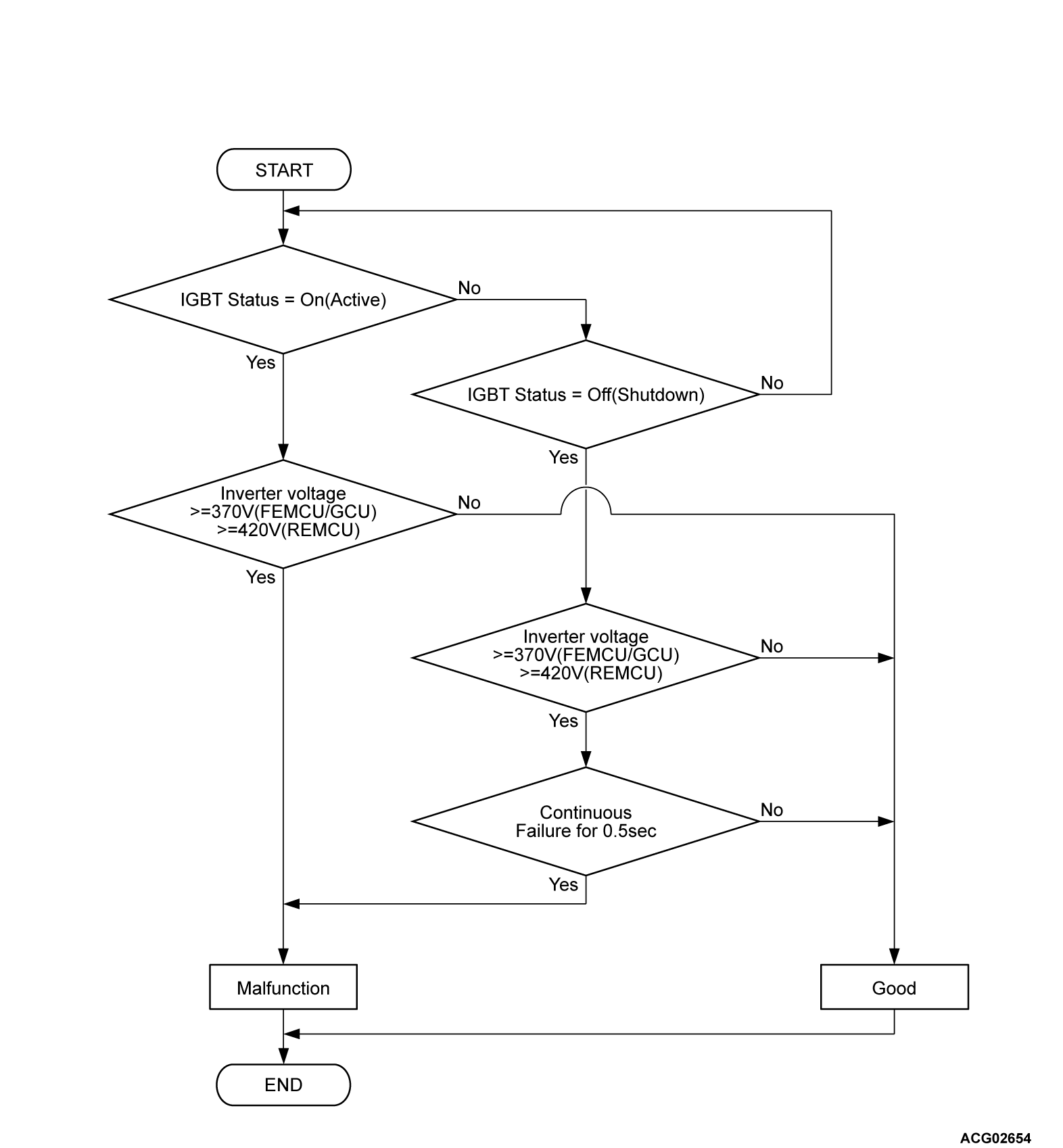
DTC P0C79: Electric motor drive voltage rises abnormally (HW detection)
| danger |
MONITOR EXECUTION
- Continuous
MONITOR EXECUTION CONDITIONS (Other monitor and Sensor)
Other Monitor (There is no temporary DTC stored in memory for the item monitored below)
- Not applicable
Sensor (The sensor below is determined to be normal)
- Drive motor inverter voltage sensor
DTC SET CONDITIONS
Check Conditions
- The IGBT status of Power drive unit (FEMCU) is on (Active).
- When the IGBT status of the power drive unit (FEMCU) is off (Shutdown), the power supply voltage of the power drive unit (FEMCU) is 8 volts to 16 volts.
Judgment Criterion
- When the IGBT status of the power drive unit (FEMCU) is on (Active), a state where the voltage-high switch * is on is detected once.
- When the IGBT status of the power drive unit (FEMCU) is off (Shutdown), a state where the voltage-high switch * is on is detected once and continues for 0.5 seconds.
| note | *: The voltage-high switch turns ON when drive motor inverter voltage is 370 volts or more. |
PROBABLE CAUSES
- The high-voltage circuit fails
- Malfunction of the power drive unit (FEMCU)
DIAGNOSIS
STEP 1. Using scan tool (M.U.T.-IIISE), check whether the other DTC is set.
Check whether the PHEV-ECU sets a DTC (Driving voltage or voltage sensor problem except P0C79).
Is the DTC set?
STEP 2. Check the high-voltage terminal.
| danger |
|
(2) Check that the following cable is tightened to the specified torque.
Is the check result normal?
![[Previous]](../../../buttons/fprev.png)
![[Next]](../../../buttons/fnext.png)


