[Previous][Next]
DTC P1037: Electric motor drive voltage too low
 
 
danger
  • When servicing the high voltage system parts, always shut off the high voltage by removing the service plug (Refer to ).
  • When servicing the high voltage system parts, always wear the protective equipment or armor to measure the high voltage (Refer to ).
 
 
MONITOR EXECUTION
  • Continuous
 
 
MONITOR EXECUTION CONDITIONS (Other monitor and Sensor)
Other Monitor (There is no temporary DTC stored in memory for the item monitored below)
  • Drive motor inverter voltage sensor
Sensor (The sensor below is determined to be normal)
  • Not applicable
 
 
DTC SET CONDITIONS
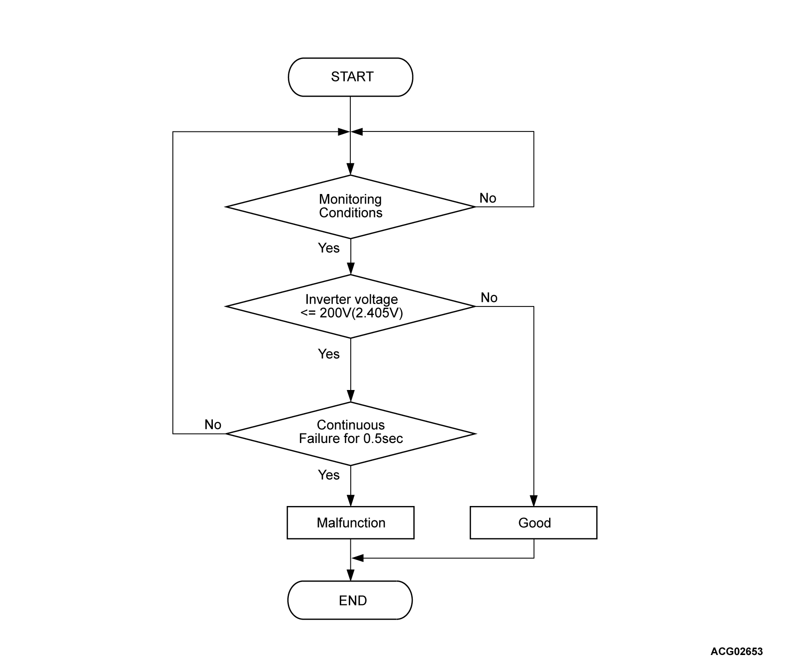
Logic Flow Chart
Check Conditions
  • The vehicle status is propulsion system active.
Judgment Criterion
  • Change of the inverter voltage is less than 200 volts (2.405 volts) for 0.5 second.
 
 
OBD-II DRIVE CYCLE PATTERN
  • Refer to Diagnostic Function - OBD-II Drive Cycle - Pattern 1 .
 
 
PROBABLE CAUSES
  • The battery pack fails
  • The high-voltage circuit fails
  • Malfunction of the REMCU
 
 
DIAGNOSIS
Required Special Tools
  • MB991223: Wiring harness set
  • MB992006: Extra fine probe
STEP 1. Using scan tool (M.U.T.-IIISE), check whether the other DTC is set.
Check if DTC P1A1B is set in the power drive unit (FEMCU), and if DTC P104D is set in the power drive unit [generator control unit (GCU)].
Is the DTC set?
Go to Step 2.
Go to Step 6.
 
STEP 2. Check the high-voltage fuse.
danger
  • Carry out the check on the high-voltage circuit while reading carefully the precautions on handling a high-voltage vehicle.
  • Wear the specified protection equipment during the check.
Check the high-voltage fuse (Refer to GROUP 54Dc - On-vehicle Service ).
Is the check result normal?
Go to Step 3.
Engage the high-voltage fuse securely, or replace it (Refer to Refer to GROUP 54Dc - On-vehicle service ). Then go to Step 9 .
 
STEP 3. Check the high-voltage circuit.
danger
  • Carry out the check on the high-voltage circuit while reading carefully the precautions on handling a high-voltage vehicle.
  • Wear the specified protection equipment during the check.
Check whether the high-voltage wiring harness is connect securely or damaged.
Is the check result normal?
Go to Step 4.
Reconnect the high-voltage wiring harness. Then go to Step 9.
 
STEP 4. Check the high-voltage circuit.
danger
  • Carry out the check on the high-voltage circuit while reading carefully the precautions on handling a high-voltage vehicle.
  • Wear the specified protection equipment during the check.
(1) Remove the service plug (Refer to ).
(2) Apply a voltage of 12 V to the CNT- terminal to turn on the charging contactor.
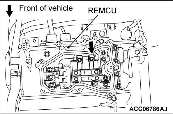
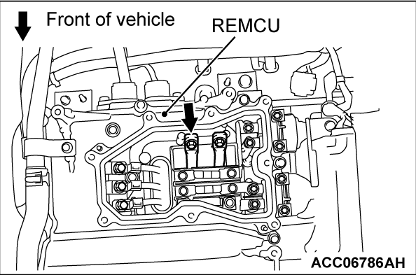
(3) Connect a high-voltage compatible multimeter between the main drive lithium-ion battery high-voltage terminal (REMCU) and the main drive lithium-ion battery service plug rear terminal.
OK: Approximately 100 - 164 V

(4) Apply a voltage of 12 V to the CNTP terminal to turn on the charging contactor.
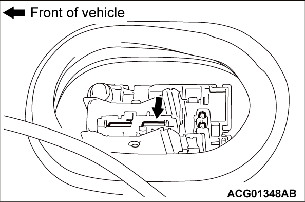
(5) Connect a high-voltage compatible multimeter between the main drive lithium-ion battery high-voltage terminal (REMCU) and the main drive lithium-ion battery service plug front terminal.
OK: Approximately 100 - 164 V

(6) Apply a voltage of 12 V to the CNT+ terminal to turn on the charging contactor.
(7) Connect a high-voltage compatible multimeter between the main drive lithium-ion battery high-voltage terminal (REMCU) and the main drive lithium-ion battery service plug front terminal.
OK: Approximately 100 - 164 V
Is the check result normal?
Go to Step 8.
Go to Step 5.
 
STEP 5. Check the high-voltage wiring harness and bus bar in the main drive lithium-ion battery.
(1) Remove the battery tray cover (Refer to GROUP 54Dc - Main Drive Lithium-ion Battery Disassembly and Assembly ).
(2) Check the high-voltage wiring harness and bus bar in the main drive lithium-ion battery for looseness or damage.
Is the check result normal?
Replace the REMCU (Refer to ). Then assemble the main drive lithium-ion battery assembly (Refer to GROUP 54Dc - Main Drive Lithium-ion Battery Disassembly and Assembly ). Then go to Step 9.
Repair the connector(s) or wiring harness. Then go to Step 9.
 
STEP 6. Check the high-voltage terminal.
danger
  • Carry out the check on the high-voltage circuit while reading carefully the precautions on handling a high-voltage vehicle.
  • Wear the specified protection equipment during the check.
Check that the following cable is tightened to the specified torque.
  • Main drive lithium-ion battery rear cable (P, N line) connection (REMCU side) (Refer to ).
Is the check result normal?
Go to Step 7.
Tighten the main drive lithium-ion battery rear cable (P, N line) to the specified torque (REMCU side) (Refer to ). Then go to Step 9.
 
STEP 7. Check the high-voltage circuit.
danger
  • Carry out the check on the high-voltage circuit while reading carefully the precautions on handling a high-voltage vehicle.
  • Wear the specified protection equipment during the check.
(1) Check that the following cable is tightened to the specified torque.
  • Main drive lithium-ion battery rear cable (P, N line) connection (main drive lithium-ion battery assembly side) (Refer to GROUP 54Dc - Main Drive Lithium-ion Battery ).
(2) Check if the main drive lithium-ion battery rear cable (P, N line) is damaged.
Is the check result normal?
Go to Step 8.
: Tighten the main drive lithium-ion battery rear cable (P, N line) to the specified torque (main drive lithium-ion battery assembly side) (Refer to GROUP 54Dc - Main Drive Lithium-ion Battery ). Then go to Step 9.
: Replace the main drive lithium-ion battery rear cable (P, N line) (Refer to <REMCU side> and GROUP 54Dc - Main Drive Lithium-ion Battery <Main drive lithium-ion battery assembly side>). Then go to Step 9.
 
STEP 8. Test the OBD-II drive cycle.
(1) Carry out a test drive with the drive cycle pattern. Refer to OBD-II Drive Cycle - Pattern 1 .
(2) Check the DTC.
Is the DTC set?
Replace the REMCU (Refer to ). Then go to Step 9.
Intermittent malfunction (Refer to GROUP 00 - How to Use Troubleshooting/Inspection Service Points - How to Cope with Intermittent Malfunctions ).
 
STEP 9. Test the OBD-II drive cycle.
(1) Carry out a test drive with the drive cycle pattern. Refer to Diagnostic Function - OBD-II Drive Cycle - Pattern 1 .
(2) Check the DTC.
Is the DTC set?
Retry the troubleshooting.
The inspection is complete.