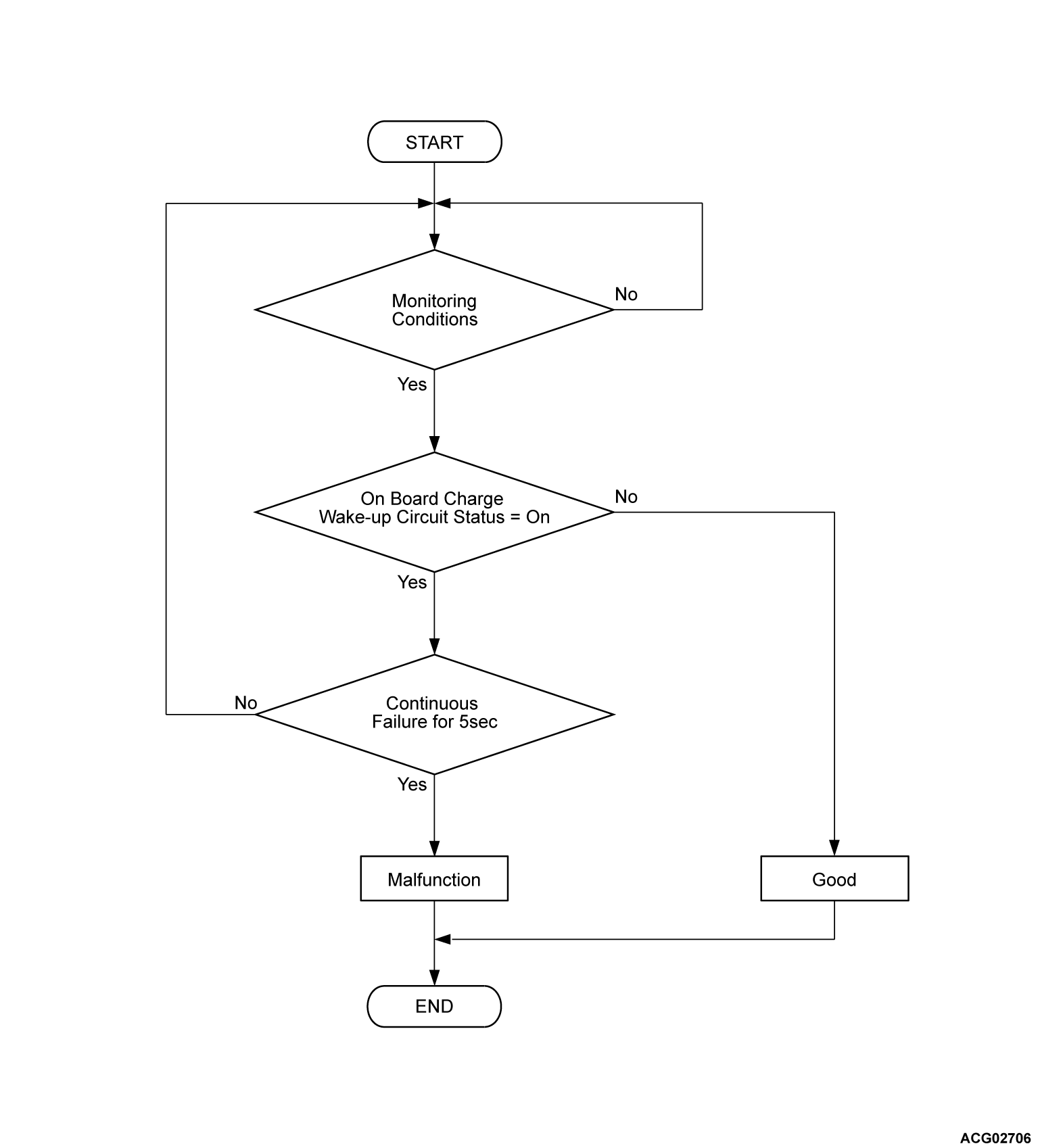
DTC P10C1: On board charge start signal LO
| caution | Whenever ECU is replaced, ensure that the CAN bus lines are normal. |
DESCRIPTIONS OF MONITOR METHODS
- These monitors will run after the ignition is on.
- PHEV-ECU monitors the on board charge wake up circuit while On board charger/DC-DC converter turns the circuit on and off.
- The PHEV-ECU detects the circuit failure based on the status of the on board charge wake up circuit during that on-off operation.
- During charging, the PHEV-ECU will not activate if the on board charge wake up circuit fails. Therefore, the on board charge wake up circuit monitor will not run during charging.
MONITOR EXECUTION
Continuous
MONITOR EXECUTION CONDITIONS (Other monitor and Sensor)
Other Monitor (There is no temporary DTC stored in memory for the item monitored below)
- Not applicable
Sensor (The sensor below is determined to be normal)
- Not applicable
Check Conditions
- The power supply mode of electric motor switch is ON.
- The PHEV-ECU power supply voltage is more than 9.0 volts.
- Time after above conditions satisfy is less than 3 seconds.
- The EV system is inactive or driving is possible
Judgment Criterion
- When a state where the on board charger/DC-DC converter wake-up circuit is ON continues for 5 seconds
PROBABLE CAUSES
- Damaged harness or connector.
- Malfunction of the on board charger/DC-DC converter.
- Malfunction of the Sub-battery management unit [BUM(SUB)].
- Malfunction of the PHEV-ECU.
DIAGNOSIS
Required Special Tools
- MB991223: Wiring harness set
- MB992006: Extra fine probe
STEP 1. Check the signal line for short to ground (On board charger/DC-DC converter, main drive lithium-ion battery, PHEV-ECU and EV remote-ECU or EV remote-ECU empty connector)
(1) Disconnect the C-41 PHEV-ECU connector, D-34 main drive lithium-ion battery connector, D-208 on board charger/DC-DC converter connector and D-31 EV remote-ECU connector, and measure at the wiring harness side.
(2) Measure the resistance between C-41 PHEV-ECU connector (terminal CHGP) and body ground.
OK: No continuity
Is the check result normal?
STEP 2. Check the signal line for short to ground (On board charger/DC-DC converter).
(1) Disconnect the D-208 on board charger/DC-DC converter connector, and measure at the on board charger/DC-DC converter side.
(2) Measure the resistance between the D-208 on board charger/DC-DC converter connector (terminal CHOT) and body ground.
OK: No continuity
(3) Measure the resistance between the D-208 on board charger/DC-DC converter connector (terminal CHOT and terminal CGND).
OK: No continuity
Is the check result normal?
STEP 3. Check the signal line for short to ground (Main drive lithium-ion battery).
(1) Disconnect the D-34 main drive lithium-ion battery connector, and measure at the main drive lithium-ion battery side.
| note | Do not disconnect the main drive lithium-ion battery connector other than D-34. |
(2) Measure the resistance between the D-34 main drive lithium-ion battery connector (terminal No.9) and body ground.
OK: No continuity
(3) Measure the resistance between the D-34 main drive lithium-ion battery connector (terminal No.9 and terminal No.6).
OK: No continuity
Is the check result normal?
STEP 4. Check the signal line for short to ground (Main drive lithium-ion battery and sub-battery management unit [BMU (SUB)]).
(1) Disassemble the main drive lithium-ion battery.
(2) Check the wiring harness between the D-34 main drive lithium-ion battery connector (terminal No.9) and the I-23 sub-battery management unit [BMU (SUB)] connector (terminal WKUP).
Is the check result normal?
STEP 5. Test the OBD-II drive cycle.
(1) Carry out a test drive with the drive cycle pattern. Refer to Diagnostic Function - OBD-II Drive Cycle - Pattern 2  .
.
 .
.(2) Check the DTC.
Is the DTC set?
![[Previous]](../../../buttons/fprev.png)
![[Next]](../../../buttons/fnext.png)


