[Previous][Next]
REMOVAL AND INSTALLATION
 
 
caution
  • When you remove/install or replace the camera, you should check the camera image on the multi around monitor "Bird-eye view." If necessary, calibrate the monitor (Refer to GROUP 54A - On-vehicle service, How to calibrate Multi Around Monitor ). <Vehicles with multi around monitor>
  • To ensure the camera image is clearly visible, wipe the lens with a damped rag and then a dry rag to remove dust, rain drops or snow.
  • Be careful not to damage the camera. Any damage may have an adverse effect on the screen image.
Pre-removal and Post-installation Operation
  • Front Door Sash Trim Removal and Installation (Refer to GROUP 52A, Door Trim .)
  • Front Door Trim Removal and Installation (Refer to GROUP 52A, Door Trim .)
  • Door Mirror Assembly Connector Connection
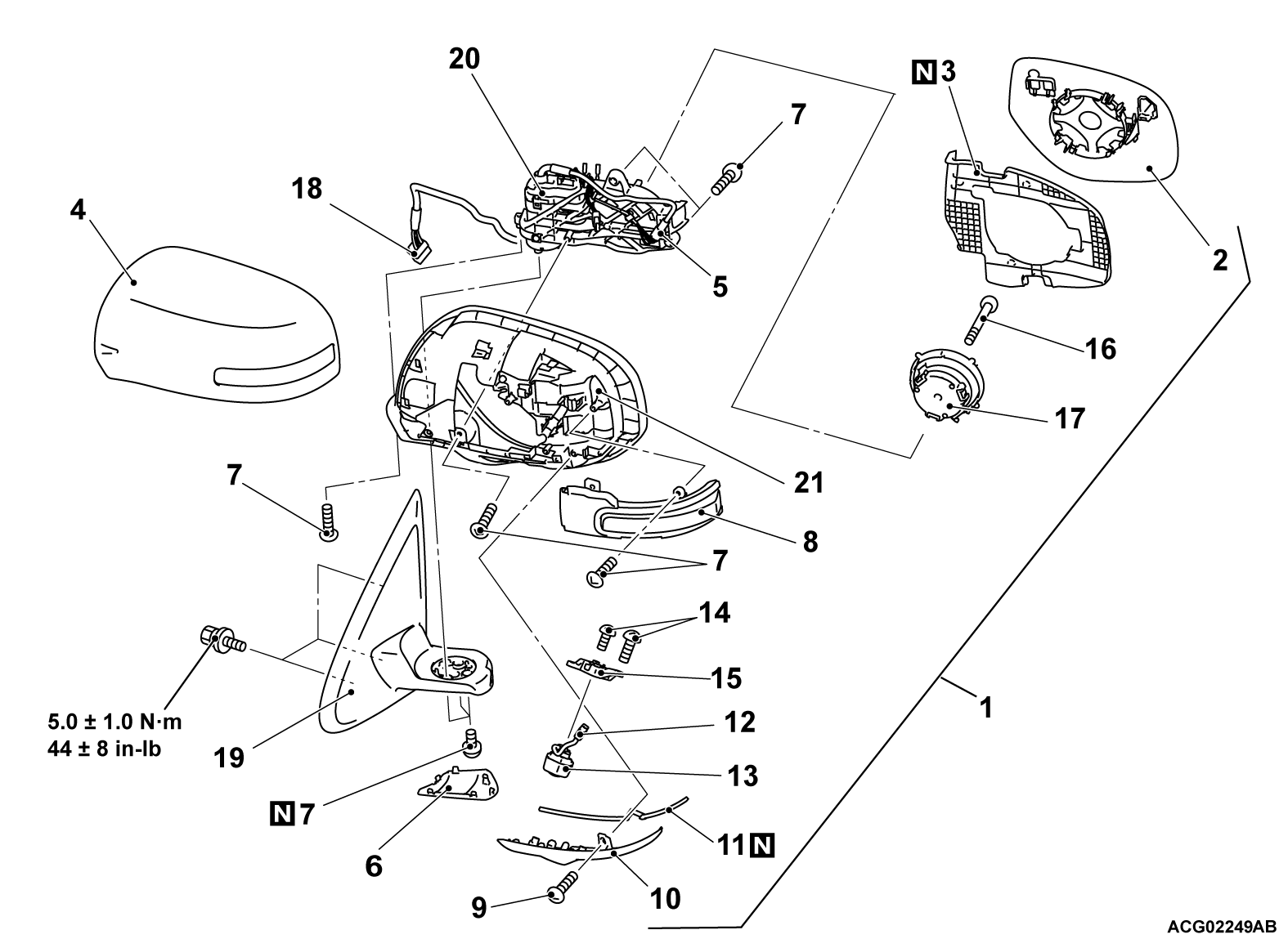
Removal steps
1.Door mirror assembly
<<A>>2.Mirror
3.Rear view mirror cushion
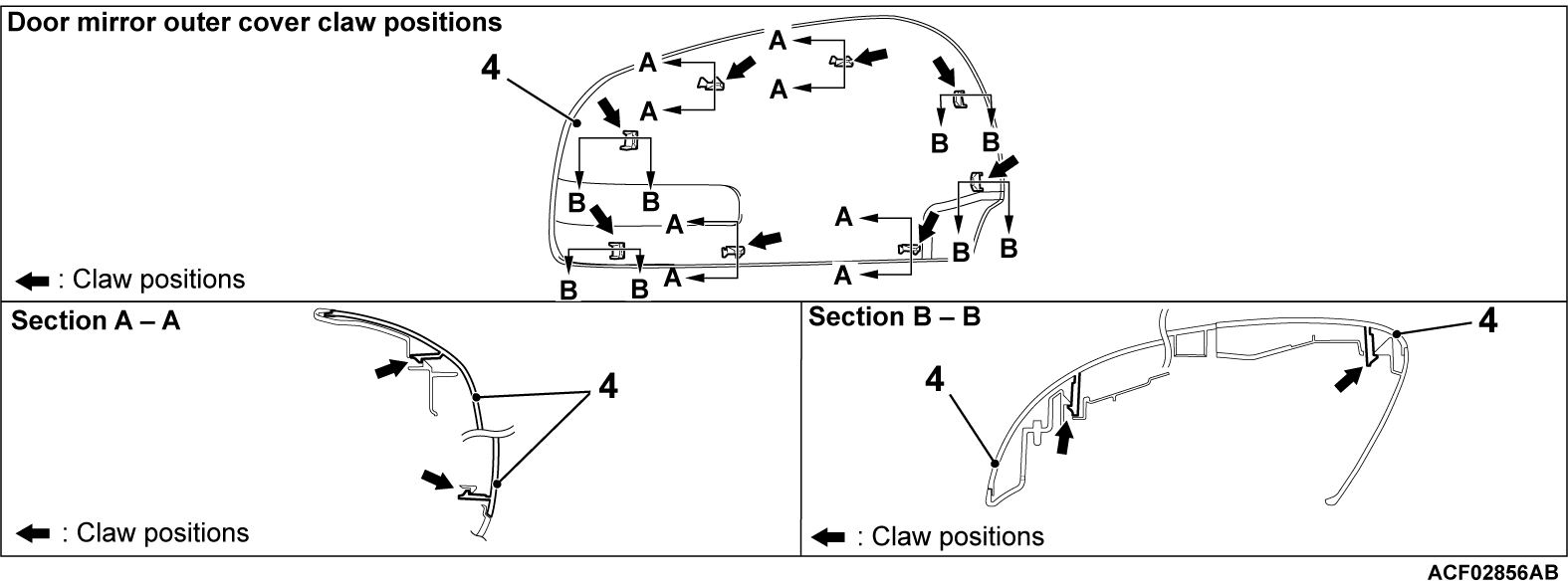
4.Door mirror outer cover
5.Connection of side turn-signal light connector
6.Door mirror base cover
7.Screw
8.Side turn-signal light assembly
9.Screw
10.Rear view mirror cover <Vehicle with multi around monitor>
11.Rear view mirror spacer <Vehicle with multi around monitor>
12.Connection of camera wiring harness connector <Vehicle with multi around monitor>
13.Side view camera <Vehicle with multi around monitor>
14.Screw
15.Camera support <Vehicle with multi around monitor>
16.Screw
17.Actuator
<<B>>>>B<<Tape
<<C>>>>A<<18.Door mirror main wiring harness connector
19.Door mirror base
20.Rear view mirror retractor motor
21.Door mirror housing
Remote controlled mirror switch removal steps
Remote controlled mirror switch (Refer to GROUP 52A, Door Trim .)
 
 
REMOVAL SERVICE POINTS
 
 
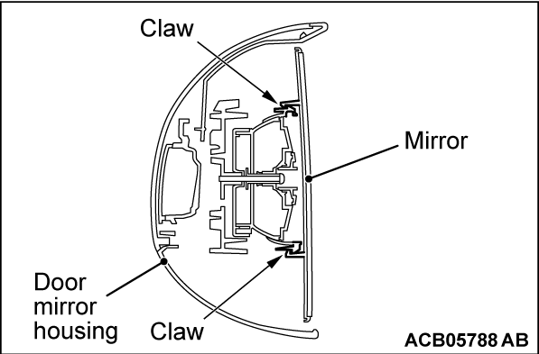
<<A>> MIRROR REMOVAL
cautionThe tab of the mirror is prone to breakage when working in cold temperatures. Always use a hair drier or the like to warm up the mirror tab and its periphery to 20°C (68°F) or higher prior to works. When the mirror is heated too quickly from its cold state, it may be broken.
1. Disengage the tab behind the mirror from the door mirror housing.
2. Disconnect the connectors of the heated mirror.


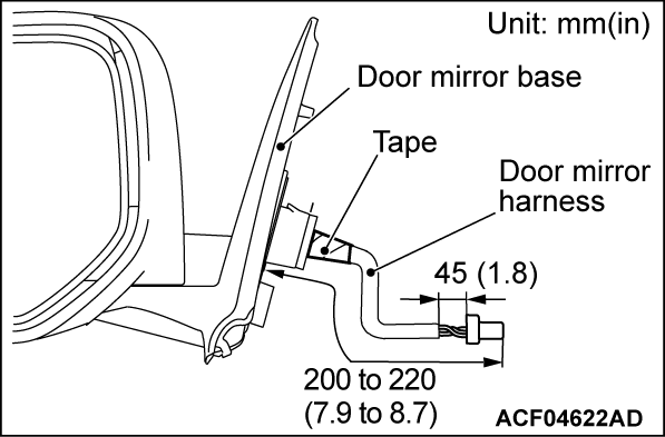
<<B>> TAPE REMOVAL
Remove the tape around the wiring harness shown in the illustration.


<<C>> DOOR MIRROR MAIN HARNESS CONNECTOR REMOVAL
Cut the wiring harness and disconnect the connector.


INSTALLATION SERVICE POINTS
 
 
>>A<< DOOR MIRROR MAIN HARNESS CONNECTOR INSTALLATION
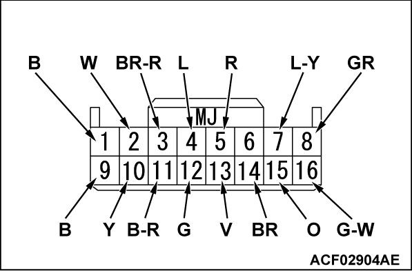
Check the wire color of the wiring harness, and insert it into the connector as shown in the illustration.

noteWire colors are indicated by alphabets as shown in the table.
CodeWire colorCodeWire colorCodeWire colorCodeWire color
BBlackLBluePUPurpleVViolet
BRBrownLGLight greenRRedWWhite
GGreenOOrangeSBSky blueYYellow
GRGrayPPinkSISilverBEBeige


>>B<< TAPE INSTALLATION
Fix the base assembly and the wiring harness at the position of the specified length with a new tape.