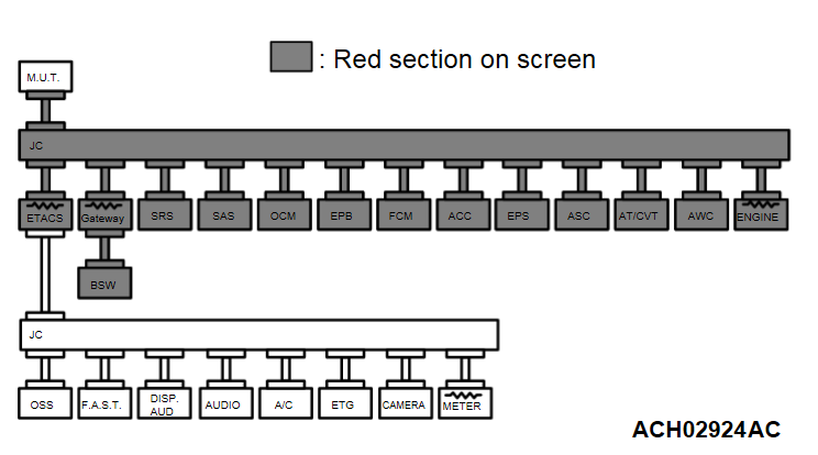
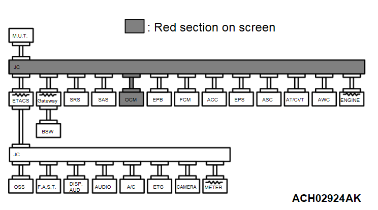
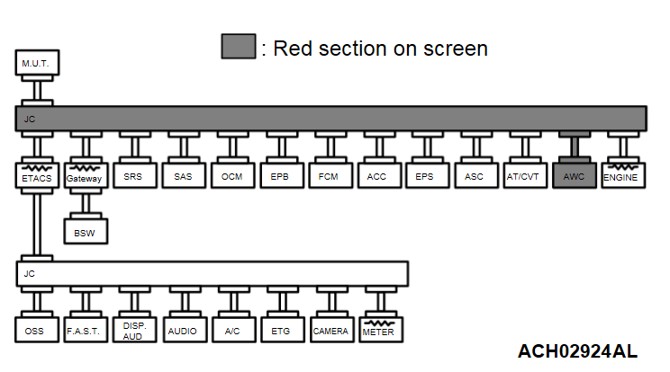
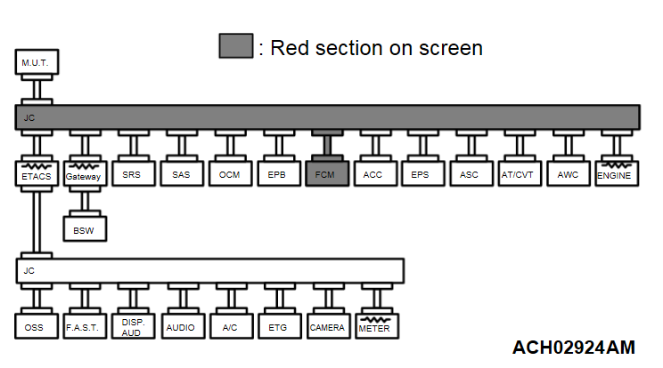
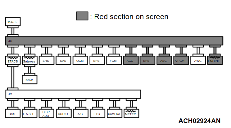
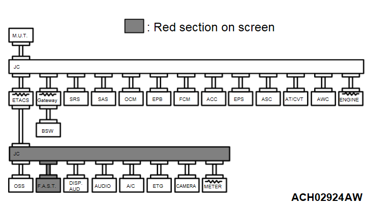
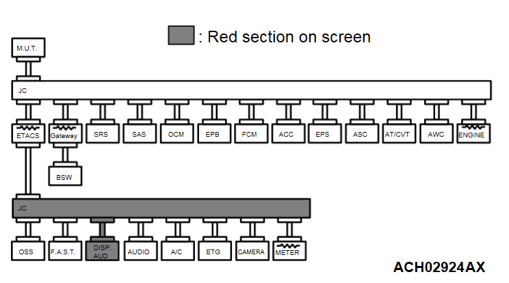
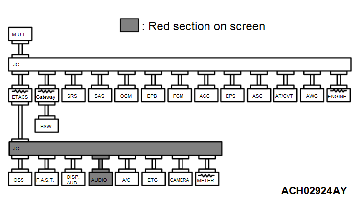
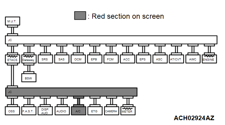
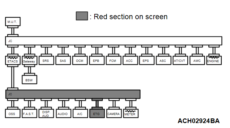
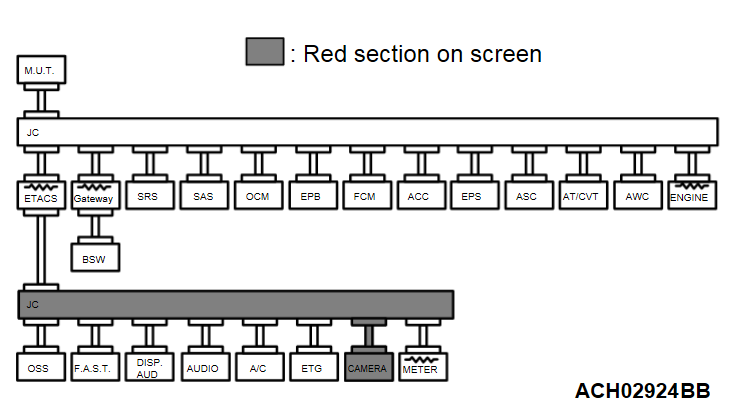
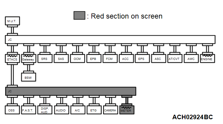
| Failure in red displayed area is estimated. | Diagnostic Item 1 Communication with no ECUs is possible (CAN-C). |  |
| - | - | Diagnostic Item 2*1 Diagnose shorts in the power supply to CAN-C. |  |
| - | - | Diagnostic Item 3*1 Diagnose shorts in the ground to CAN-C. |  |
| - | - | Diagnostic Item 4*1 Diagnose shorts between CAN_H and L lines (CAN-C). |  |
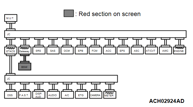
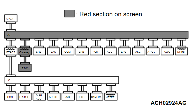
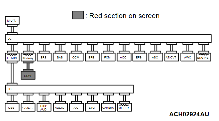
| CAN-C*3: Failure in red displayed area is estimated. | Diagnostic Item 5 Communication with no ECUs is possible (GW-CAN-C). <Vehicles with Blind Spot Warning [BSW] (with Lane Change Assist) system> |  |
| - | - | Diagnostic Item 6*2 Diagnose shorts in the power supply to GW-CAN-C. <Vehicles with Blind Spot Warning [BSW] (with Lane Change Assist) system> |  |
| - | - | Diagnostic Item 7*2 Diagnose shorts in the ground to GW-CAN-C. <Vehicles with Blind Spot Warning [BSW] (with Lane Change Assist) system> |  |
| - | - | Diagnostic Item 8*2 Diagnose shorts between CAN_H and L lines (GW-CAN-C). <Vehicles with Blind Spot Warning [BSW] (with Lane Change Assist) system> |  |
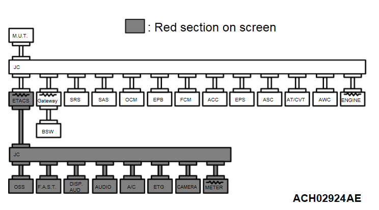
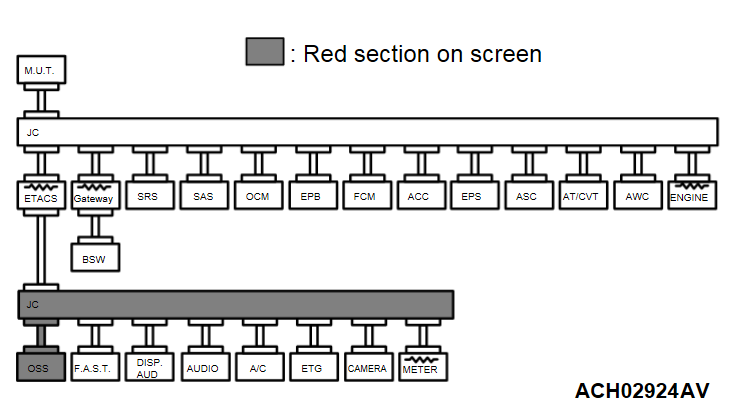
| CAN-C-Mid: Failure in red displayed area is estimated. | Diagnostic Item 9 Communication with no ECUs is possible (CAN-C-Mid). |  |
| - | - | Diagnostic Item 10*2 Diagnose shorts in the power supply to CAN-C-Mid. |  |
| - | - | Diagnostic Item 11*2 Diagnose shorts in the ground to CAN-C-Mid. |  |
| - | - | Diagnostic Item 12*2 Diagnose shorts between CAN_H and L lines (CAN-C-Mid). |  |
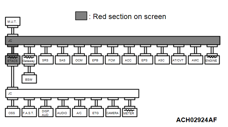
| CAN-C: Failure in red displayed area is estimated. | Diagnostic Item 13 Diagnose when the scan tool cannot receive the data sent by ETACS-ECU. |  |
| CAN-C: Failure in red displayed area is estimated. | Diagnostic Item 14 Diagnose when the scan tool cannot receive the data sent by gateway-ECU. <Vehicles with Blind Spot Warning [BSW] (with Lane Change Assist) system> |  |
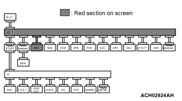
| CAN-C: Failure in red displayed area is estimated. | Diagnostic Item 15 Diagnose when the scan tool cannot receive the data sent by SRS-ECU. |  |
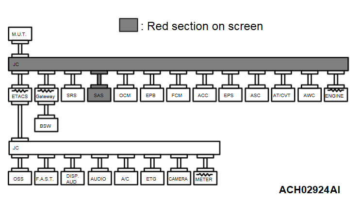
| CAN-C: Failure in red displayed area is estimated. | Diagnostic Item 16 Diagnose when the scan tool cannot receive the data sent by steering wheel sensor |  |
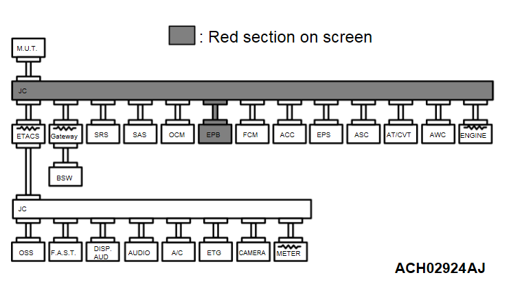
| CAN-C: Failure in red displayed area is estimated. | Diagnostic Item 17 Diagnose when the scan tool cannot receive the data sent by electric parking brake ECU. <Vehicles with electric parking brake> |  |
| CAN-C: Failure in red displayed area is estimated. | Diagnostic Item 18 Diagnose when the scan tool cannot receive the data sent by occupant classification-ECU. |  |
| CAN-C: Failure in red displayed area is estimated. | Diagnostic Item 19 Diagnose when the scan tool cannot receive the data sent by AWD-ECU <Vehicles without S-AWC> or AWC-ECU <Vehicles with S-AWC>. <AWD> |  |
| CAN-C: Failure in red displayed area is estimated. | Diagnostic Item 20 Diagnose when the scan tool cannot receive the data sent by FCM/LDW/AHB-ECU. <Vehicles with FCM> |  |
| CAN-C: Failure in red displayed area is estimated. | Diagnostic Item 21 Diagnose the lines between the joint connectors (CAN3 and CAN1). |  |
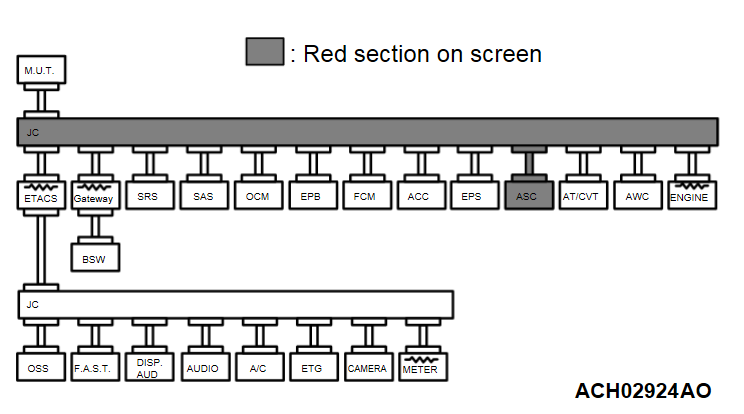
| CAN-C: Failure in red displayed area is estimated. | Diagnostic Item 22 Diagnose when the scan tool cannot receive the data sent by ASC-ECU. |  |
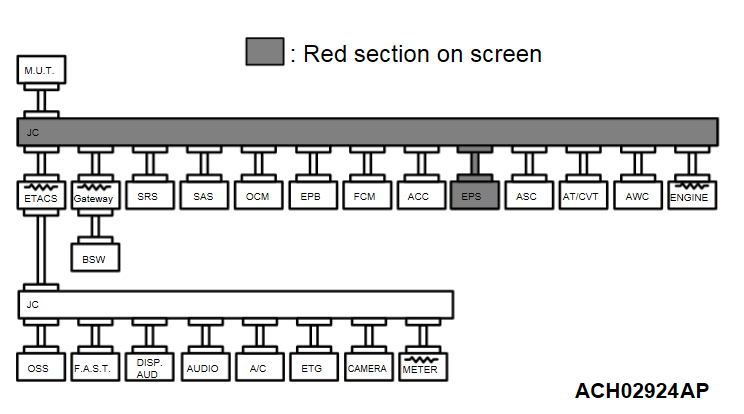
| CAN-C: Failure in red displayed area is estimated. | Diagnostic Item 23 Diagnose when the scan tool cannot receive the data sent by EPS-ECU. |  |
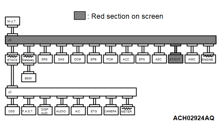
| CAN-C: Failure in red displayed area is estimated. | Diagnostic Item 24 Diagnose when the scan tool cannot receive the data sent by transaxle control module (TCM). |  |
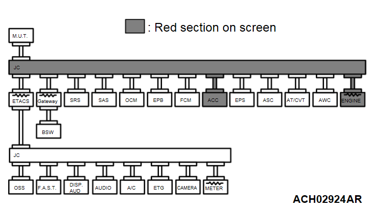
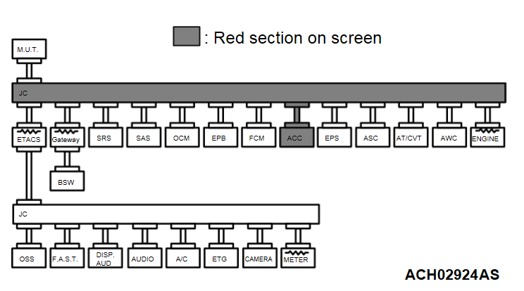
| CAN-C: Failure in red displayed area is estimated. | Diagnostic Item 25 Diagnose the lines between the joint connectors (CAN1 and CAN2). <Vehicles with ACC> |  |
| CAN-C: Failure in red displayed area is estimated. | Diagnostic Item 26 Diagnose when the scan tool cannot receive the data sent by ACC-ECU. <Vehicles with ACC> |  |
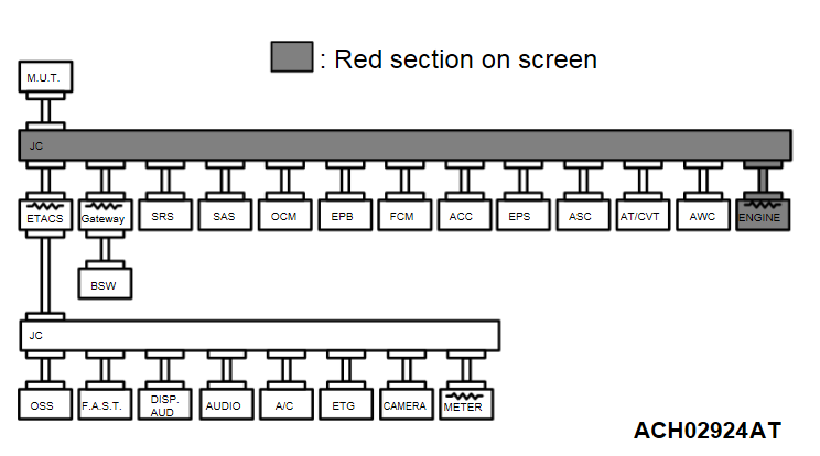
| CAN-C: Failure in red displayed area is estimated. | Diagnostic Item 27 Diagnose when the scan tool cannot receive the data sent by engine control module (ECM). |  |
| CAN-C*3: Failure in red displayed area is estimated. | Diagnostic Item 28 Diagnose when the scan tool cannot receive the data sent by BSW-ECU. <Vehicles with Blind Spot Warning [BSW] (with Lane Change Assist) system> |  |
| CAN-C-Mid: Failure in red displayed area is estimated. | Diagnostic Item 29 Diagnose when the scan tool cannot receive the data sent by OSS-ECU. <Vehicles with OSS> |  |
| CAN-C-Mid: Failure in red displayed area is estimated. | Diagnostic Item 30 Diagnose when the scan tool cannot receive the data sent by KOS-ECU. <Vehicles with KOS> |  |
| CAN-C-Mid: Failure in red displayed area is estimated. | Diagnostic Item 31 Diagnose when the scan tool cannot receive the data sent by smartphone link display audio <Vehicles with smartphone link display audio> or display audio <Vehicles with display audio>. |  |
| CAN-C-Mid: Failure in red displayed area is estimated. | Diagnostic Item 32 Diagnose when the scan tool cannot receive the data sent by 1CD audio. <Vehicles with 1CD audio> |  |
| CAN-C-Mid: Failure in red displayed area is estimated. | Diagnostic Item 33 Diagnose when the scan tool cannot receive the data sent by A/C-ECU. |  |
| CAN-C-Mid: Failure in red displayed area is estimated. | Diagnostic Item 34 Diagnose when the scan tool cannot receive the data sent by power liftgate control unit. <Vehicles with power liftgate> |  |
| CAN-C-Mid: Failure in red displayed area is estimated. | Diagnostic Item 35 Diagnose when the scan tool cannot receive the data sent by camera-ECU. <Vehicles with multi around monitor> |  |
| CAN-C-Mid: Failure in red displayed area is estimated. | Diagnostic Item 36 Diagnose when the scan tool cannot receive the data sent by combination meter. |  |
![[Previous]](../../../buttons/fprev.png)
![[Next]](../../../buttons/fnext.png)
