[Previous][Next]
REMOVAL AND INSTALLATION
 
 
danger
  • The SRS-ECU adopts the rollover specification that the curtain air bag and seat belt pre-tensioner operate at the occurrence of rollover. Therefore, do not tilt the vehicle to the right and left with the ignition switch "ON" or tilt the SRS-ECU to the right and left with the ignition switch "ON" and the harness installed.
warning
  • Never connect the negative battery terminal when the SRS-ECU is not installed securely. If you fail to follow this instruction, the air bag may deploy unintentionally, possibly causing a serious injury.
  • Never attempt to disassemble or repair the SRS-ECU. If faulty, replace it.
  • Do not drop or subject the SRS-ECU to impact or vibration. If denting, cracking, deformation, or rust are discovered in the SRS-ECU, replace it with a new SRS-ECU.
  • After deployment of an air bag, replace the SRS-ECU with a new one.
  • Never use an ohmmeter on or near the SRS-ECU, and use only the special test equipment described here .
caution
  • When the SRS-ECU is replaced, chassis number writing and coding must be performed. Perform the coding when SRS-ECU stores diagnostic trouble code No. U1195 (coding incomplete). Refer to the "Scan tool (M.U.T.-III) operation manual" and perform coding.
Pre-removal operation
  • Turn the ignition switch to the LOCK (OFF) position.
Removal steps
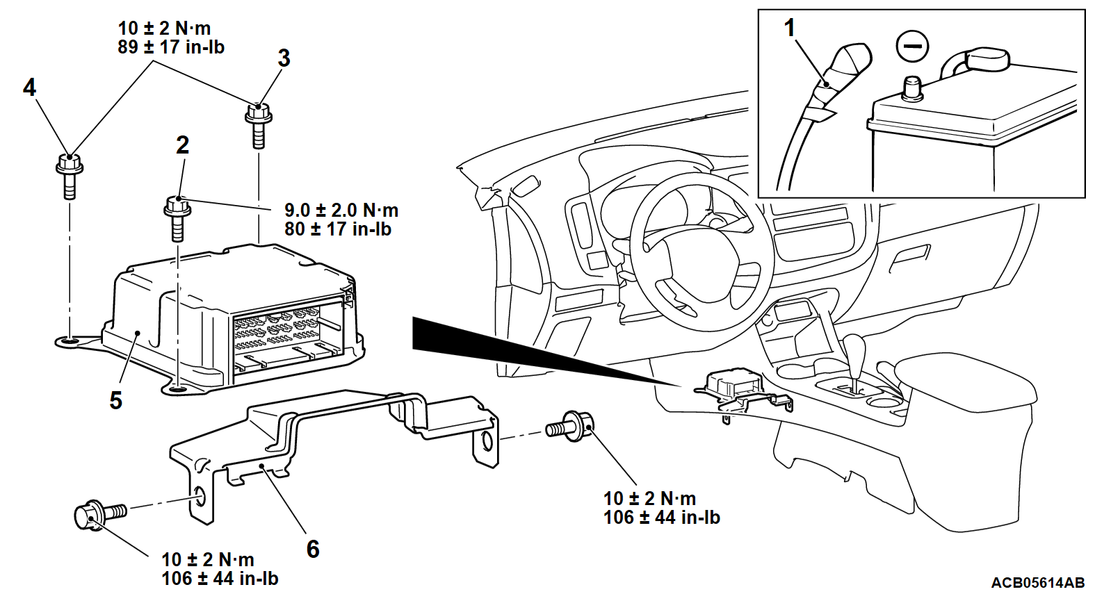
<<A>>1.Negative (-) battery cable
Shift lever panel assembly (Refer to GROUP 52A - Front Floor Console Assembly ).
Rear heater duct A (Refer to GROUP 55 - Duct ).
2.SRS-ECU mounting bolt (ground bolt)
3.SRS-ECU mounting bolt
4.SRS-ECU mounting bolt
<<B>>5.SRS-ECU
6.Control unit cover
Installation steps
6.Control unit cover
>>A<<5.SRS-ECU
4.SRS-ECU mounting bolt
3.SRS-ECU mounting bolt
>>B<<2.SRS-ECU mounting bolt (ground bolt)
Shift lever panel assembly (Refer to GROUP 52A - Front Floor Console Assembly ).
Rear heater duct A (Refer to GROUP 55 - Duct ).
1.Negative (-) battery cable
>>C<<Post-installation inspection
 
 
REMOVAL SERVICE POINTS
 
 
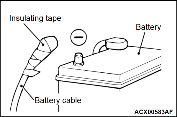
<<A>> NEGATIVE (-)BATTERY CABLE DISCONNECTION
dangerWait at least 60 seconds after disconnecting the battery cable before doing any further work (Refer to ).
warningBattery posts, terminals and related accessories contain lead and lead compounds. WASH HANDS AFTER HANDLING.
Disconnect the negative (-) battery cable from the battery and tape the terminal to prevent accidental connection and air bag(s) deployment.


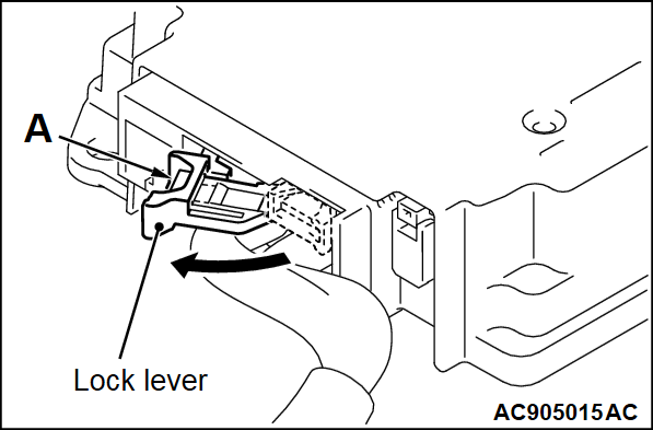
<<B>> SRS-ECU REMOVAL
While pushing the part "A" indicated in the figure of the harness side connector, turn the lock lever to the direction of the arrow to release the lock lever.


INSTALLATION SERVICE POINTS
 
 
>>A<< SRS-ECU INSTALLATION
warningThe SRS may not activate if the SRS-ECU is not installed properly, which could result in serious injury or death to the vehicle's driver or front passenger.


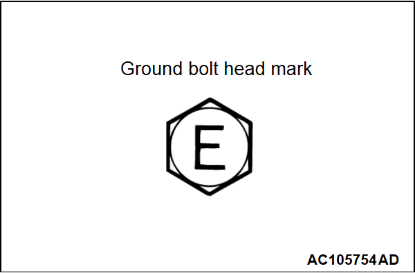
>>B<< SRS-ECU MOUNTING BOLT (GROUND BOLT) INSTALLATION
Check the head mark "E" and install the ground bolt.


>>C<< POST-INSTALLATION INSPECTION
1. Connect the negative (-) battery cable.
2. Turn the ignition switch to the "ON" position.
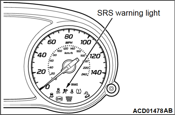
3. Check that the SRS warning light is illuminated for 6 to 8 seconds, and extinguished afterward.
4. If the light does not extinguish, perform the troubleshooting (Refer to ).