[Previous][Next]
DISASSEMBLY AND REASSEMBLY
 
 
caution
  • When you remove/install or replace the camera, you should check the camera image on the multi around monitor "Bird-eye view." If necessary, calibrate the monitor (Refer to GROUP 54A - On-vehicle service, How to calibrate Multi Around Monitor ). <Vehicles with multi around monitor>
  • To ensure the camera image is clearly visible, wipe the lens with a damped rag and then a dry rag to remove dust, rain drops or snow.
  • Be careful not to damage the camera. Any damage may have an adverse effect on the screen image.
Post-installation Operation
Front Fog light Aiming Adjustment (Refer to GROUP 54A, Fog light - On-vehicle Service ) <Vehicles with Fog Light>.
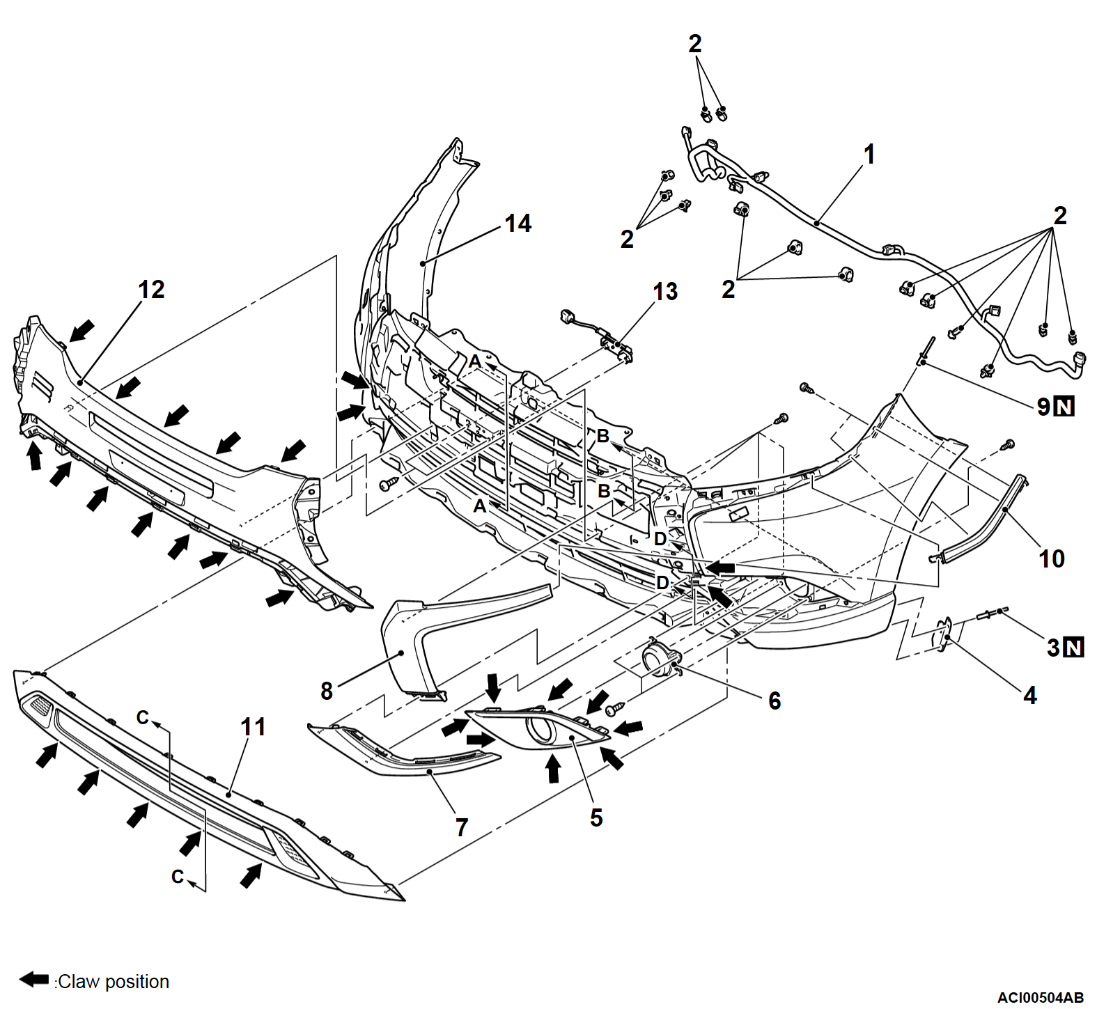
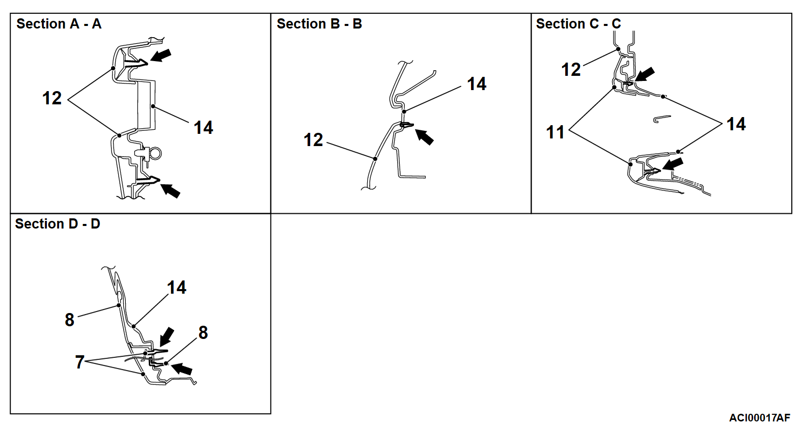
Disassembly steps
1.Front bumper light wiring harness
2.Harness clamp
<<A>>>>A<<3.Rivet
4.Front bumper reinforcement
5.Front fog light bezel
6.Front fog light cover <Vehicles without front fog light> or Front fog light assembly <Vehicles with front fog light> (Refer to GROUP 54A, Fog light )
7.Front bumper side lower garnish
8.Front bumper side center garnish
<<A>>>>A<<9.Rivet
10.Front bumper side upper garnish
11.Front bumper extension
12.Front bumper center cover
13.Front view camera
14.Front bumper face
 
 
DISASSEMBLY SERVICE POINT
 
 
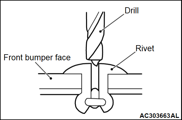
<<A>> RIVETS REMOVAL
Use a drill [Φ 4.0 mm (0.16 in)] to make a hole in the rivet to break it, and remove the rivet.


REASSEMBLY SERVICE POINT
 
 
>>A<< RIVETS INSTALLATION
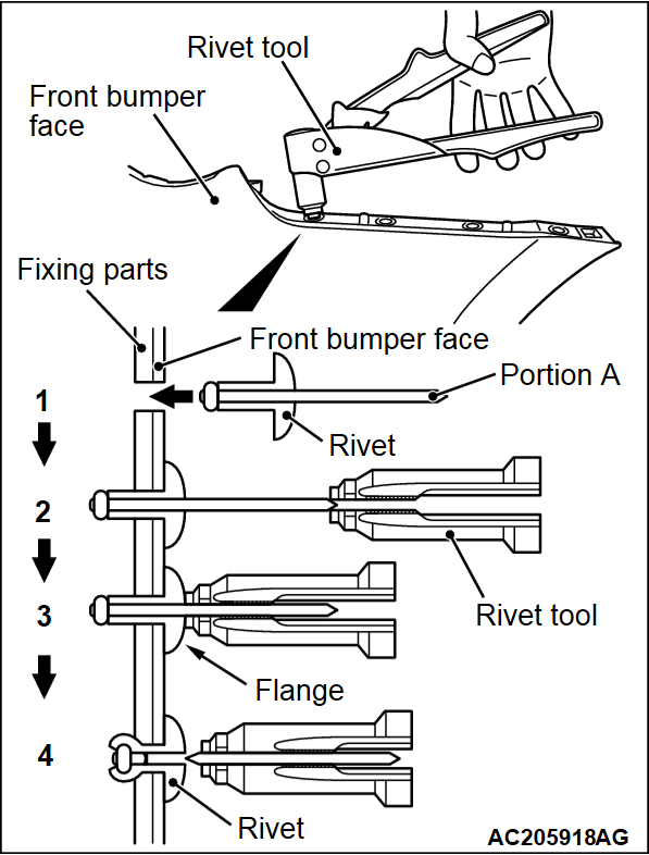
Use a rivet tool shown as in the illustration to connect the parts with rivets by the following procedures:
1. Insert the rivet into a corresponding location.
2. Set the rivet tool at a portion A of rivet.
3. While pushing the flange surface of the rivet onto parts to be fixed with the rivet tool, press the handle of the tool.
4. Thin part of portion A of the rivet will be cut off and the part is fixed in position.