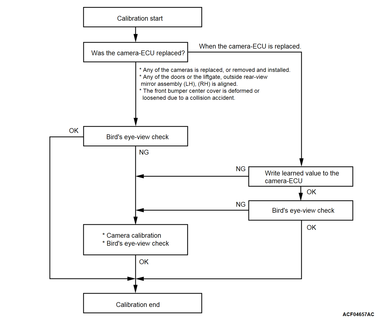
Calibration
Calibrate according to the procedure below after the following operation is performed:
- Replacement of the camera-ECU
- Removal and installation/replacement of a camera
- Any of the door or the liftgate, Outside rear-view mirror assembly (LH), (RH) is aligned.
- The front bumper center cover is deformed or loosened due to a collision accident.
How to check the image screen visually
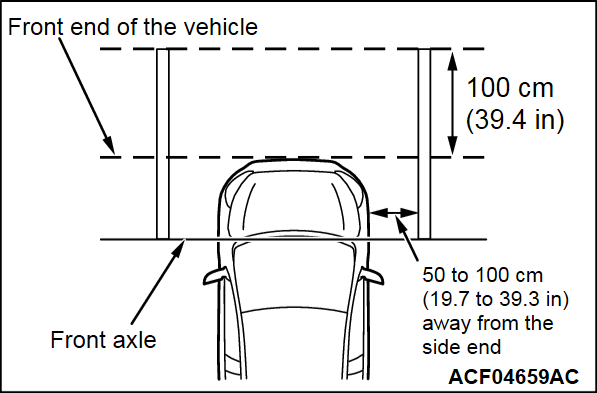
Checking image from the front view camera
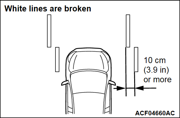
1. Draw white 10 cm (3.9 inches)-wide lines next to either side of the vehicle.
2. Press the camera switch on the steering wheel remote control switch (LH) to display the bird's eye-view on the multivision display.
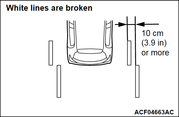
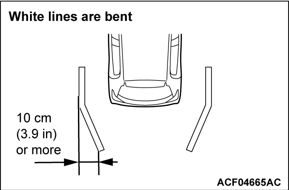
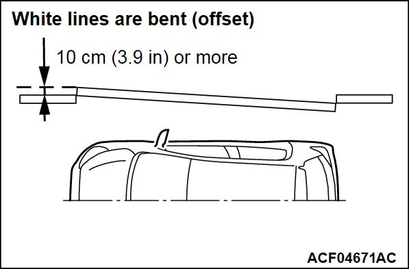
3. Two white lines should be displayed as "straight line". When the line is broken or offset, calibrate the cameras.
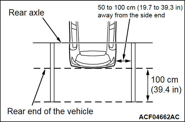
Checking image from the rear view camera
1. Draw white 10 cm (3.9 inches)-wide lines next to either side of the vehicle.
2. Press the camera switch on the steering wheel remote control switch (LH) to display the bird's eye-view on the multivision display.
3. Two white lines should be displayed as "straight line". When the line is broken or offset, calibrate the cameras.
Checking image from the side view camera (RH)
| note | The left side camera must be also calibrated. |
1. Draw white 10 cm (3.9 inches)-wide lines next to the right side of the vehicle.
2. Press the camera switch on the steering wheel remote control switch (LH) to display the bird's eye-view on the multivision display.
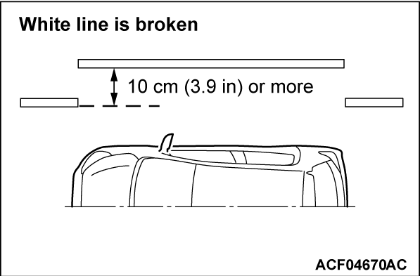
3. Two white lines should be displayed as "straight line". When the line is broken or offset, calibrate the cameras.
How to write learned value to the camera-ECU
When the camera is replaced, write a learned value to the new camera-ECU according to the procedure below.
1.
| caution | To prevent damage to scan tool (M.U.T.-III), always turn the ignition switch to the "LOCK" (OFF) position before connecting or disconnecting scan tool (M.U.T.-III). |
2. Select "Write learned value(Changed ECU)" and then "Learned value Read & save" in the special functions for the multi-around monitor system to save the learned value, which is stored in the current camera-ECU, to the scan tool (M.U.T.-III).
| note | If the learned value cannot be read, replace the camera-ECU and then calibrate the camera. |
4. Select "Write learned value(Changed ECU)" and then "Saved learned value writing" in the special functions to write the learned value, which is stored in the scan tool (M.U.T.-III), to the camera-ECU.
5. If any problems are not found on the screen, the calibration is complete. If any problem is found, calibrate the camera.
How to calibrate a camera
Required Special Tool:
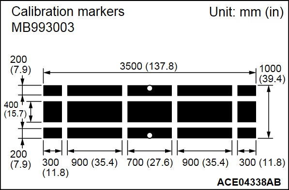
- MB993003: Calibration marker
| caution |
|
1. When the camera-ECU is replaced, first write a learned value to the camera-ECU.
2. Park the vehicle on a level surface.
| note | Prevent sun light rays from interfering with the camera, otherwise the monitor screen will be reflected in white. Ideally, the brightness of a road surface should be low (such as black). |
3. One person should sit on the driver's seat.
4.
| caution | To prevent damage to scan tool (M.U.T.-III), always turn the ignition switch to the "LOCK" (OFF) position before connecting or disconnecting scan tool (M.U.T.-III). |
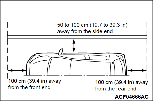
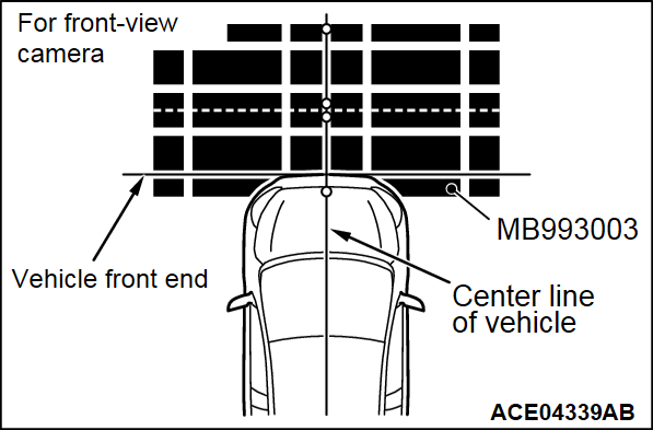
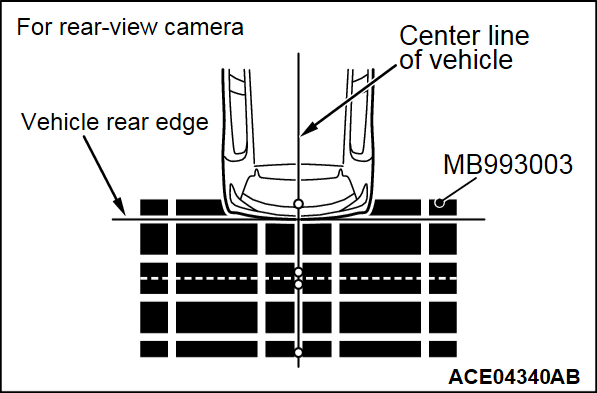
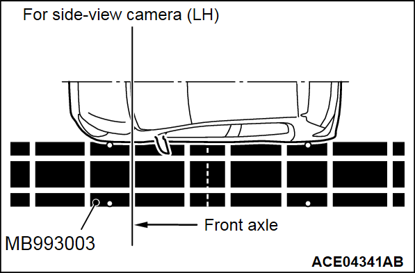
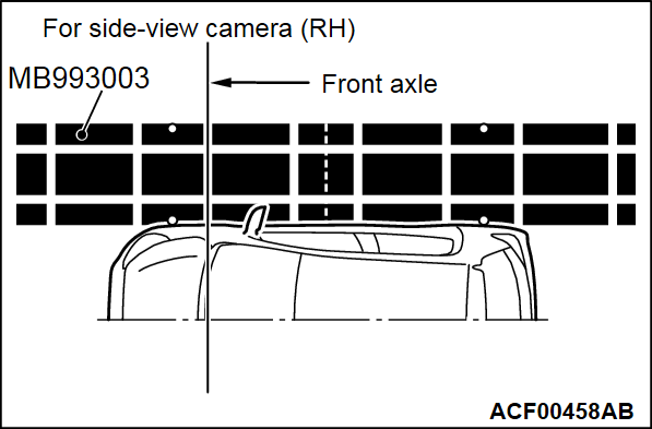
5. Position the calibration markers (MB993003) as shown.
- Position the calibration markers in respect to the relevant camera only.
| note |
|
6. Turn "ON → OFF → ON" the ignition switch position.
7. Use the scan tool (M.U.T.-III) to calibrate the camera.
| note | When you execute the calibration, all calibration-related data will be erased from the ECU. |
8. Select "Calibration" in the "special function" for the multi-around monitor system.
9. Select a camera to be calibrated on the data list located to the left of the calibration screen, and then press "OK."
|
| Item No. | Item name | Contents |
| 1 | Front camera | Calibrate only the selected camera. |
| 2 | Rear camera | |
| 3 | Left side camera | |
| 4 | Right side camera |
10. Select the camera being calibrated in the confirmation screen, and the press "OK."
11. Press the "OK" button after the execution screen is displayed.
12. When the calibration has completed successfully, "Completed" will be displayed on the data list item No.13.
13. If the calibration has failed, "Error" will be displayed on the data list item No.13. For details of errors, refer to "Calibration error table."
14. If any problems are not found on the screen, the calibration is complete. If any problems are found, repeat the calibration.
Calibration error table
| Item No. | Item name | Error contents | Troubleshooting |
| 14 | Coding not comp/Setting err.flag | The variant coding for the ETACS-ECU has not been implemented. | Check whether DTC No. U1195 is set. If yes, diagnose the system according to the DTC. |
| Requirements for the calibration are not satisfied. | Check whether the requirements for the calibration are satisfied.
| ||
| 15 | Door open detection flag | Any of the doors and liftgate are open. | Check that any of the doors and liftgate are closed. If no, close the door or the liftgate. |
| 16 | Front camera error flag | The front-view camera does not recognize either of the calibration markers precisely. |
|
| 17 | Rear camera error flag | The rear-view camera does not recognize either of the calibration markers precisely. | |
| 18 | Left side camera error flag | The side-view camera (LH) does not recognize either of the calibration markers precisely. | |
| 19 | Right side camera error flag | The side-view camera (RH) does not recognize either of the calibration markers precisely. | |
| 20 | Flash ROM writing error flag | Internal malfunction of camera-ECU. | |
| 21 | SD-RAM error flag | ||
| 22 | EEPROM writing error flag |
![[Previous]](../../../buttons/fprev.png)
![[Next]](../../../buttons/fnext.png)
