DTC P2721: Malfunction of Select Pressure Solenoid Valve (high input)
DIAGNOSTIC FUNCTION
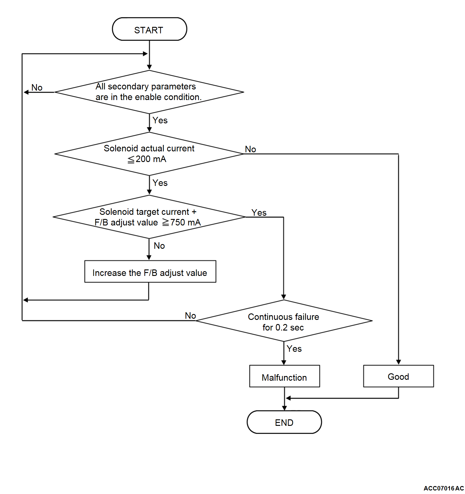
The TCM monitors the select pressure solenoid valve circuit for open or short to power supply.
DESCRIPTIONS OF MONITOR METHODS
- All the conditions listed below remain for 0.2 seconds.
- The select pressure solenoid valve command current is 750 mA or more.
- The select pressure solenoid valve current, which the TCM monitors, is 200 mA or less.
- The solenoid valve drive circuit is not shorted to ground.
- All the conditions listed below remain for 0.2 seconds.
- The solenoid valve drive circuit is not shorted to ground.
- The solenoid valve drive circuit system is defective.
MONITOR EXECUTION
- Voltage of battery: 10 volts or more.
MONITOR EXECUTION CONDITIONS (OTHER MONITOR AND SENSOR)
Other Monitor (There is no temporary DTC stored in memory for the item monitored below)
- P0730: Incorrect gear ratio
Sensor (The sensor below is determined to be normal)
- Not applicable
DTC SET CONDITIONS
Check Conditions
- Voltage of battery: 10 volts or more.
Judgment Criteria
- Select pressure solenoid valve actual current: 200 mA or less (0.2 seconds).
- Select pressure solenoid valve target current + F/B adjust value: 750 mA or more (0.2 seconds).
OBD-II DRIVE CYCLE PATTERN
Ignition switch: ON (start the engine and keep it for 5 seconds or more)
PROBABLE CAUSES
- Malfunction of the valve body assembly (Faulty select pressure solenoid valve)
- Damaged wiring harness and connectors
- Malfunction of TCM
DIAGNOSIS
STEP 1. Voltage measurement at TCM connector (LBLS terminal)
(1) Disconnect the TCM connector, and measure at the wiring harness side.
(2) Turn the ignition switch to the "ON" position.
(3) Measure the voltage between the TCM connector (LBLS terminal) and body ground.
OK: 0 V
Is the check result normal?
: Repair the connector(s) or the wiring harness (LBLS line between the CVT assembly connector and the TCM connector).
STEP 2. Check for open circuit in LBLS line between the CVT assembly connector and the TCM connector
STEP 3. Select pressure solenoid valve check
![[Previous]](../../../buttons/fprev.png)
![[Next]](../../../buttons/fnext.png)


