DTC P0300: Random/Multiple Cylinder Misfire Detected
TECHNICAL DESCRIPTION
- If a misfire occurs while the engine is running, the engine speed changes for an instant.
- The ECM checks for such changes in engine speed.
DESCRIPTIONS OF MONITOR METHODS
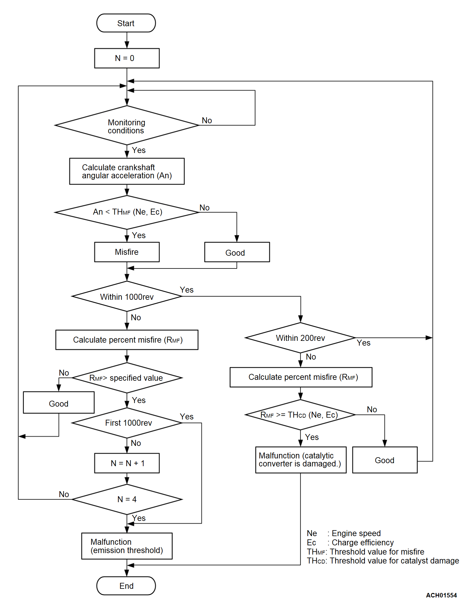
Monitor angular acceleration of crankshaft and detect malfunction when negative variation of the angular acceleration is large.
MONITOR EXECUTION
- Continuous
MONITOR EXECUTION CONDITIONS (Other monitor and Sensor)
Other Monitor (There is no temporary DTC set in memory for the item monitored below)
- Not applicable
Sensor (The sensor below is determined to be normal)
- Camshaft position sensor
- Mass airflow sensor
- Engine coolant temperature sensor
- Intake air temperature sensor
- Barometric pressure sensor
- Throttle position sensor
Check Conditions
- Engine speed is between 438 and 6,656 r/min.
- Engine coolant temperature is more than -10°C (14°F). (However, 20°C (68°F) when the engine coolant temperature at engine start is -10°C (14°F) or less).
- Barometric pressure is higher than 76 kPa (22.4 in.Hg).
- The engine load is with in the positive torque load.
- Adaptive learning is complete for the vane which generates a crankshaft position signal.
- While the engine is running, excluding sudden acceleration/deceleration and fuel shut-off operation.
Judgment Criterion (change in the angular acceleration of the crankshaft is used for misfire detection).
- Misfire has occurred more frequently than allowed during the last 200 revolutions [when the catalyst temperature is higher than 1,000°C (1,832°F)].
or
- Misfire has occurred in 1.7 percent or more in the first 1,000 revolutions from engine start-up (corresponding to 1.5 times the limit of emission standard).
or
- After the first 1,000 revolutions, the following criterion is satisfied 4 times cumulatively.
- Misfire counts per 1,000 revolutions exceeds in 1.7 percent.
FAIL-SAFE AND BACKUP FUNCTION
- The supply of fuel to the misfiring cylinder can possibly be cut.
TROUBLESHOOTING HINTS (The most likely causes for this code to be set are:)
- Included air due to lack of fuel
- Ignition system related part(s) failed.
- Poor crankshaft position sensor.
- Incorrect air/fuel ratio.
- Spark plug failed.
- Low compression pressure.
- Skipping of timing belt teeth.
- EGR valve (stopper motor) failed.
- ECM failed.
DIAGNOSIS
Required Special Tools:
- MB992744: Vehicle Communication Interface-Lite (V.C.I.-Lite)
- MB992745: V.C.I.-Lite Main Harness A
- MB992747: V.C.I.-Lite USB Cable Short
- MB992748: V.C.I.-Lite USB Cable Long
- MB991958: Scan Tool (M.U.T.-III Sub Assembly)
- MB991824: Vehicles Communication Interface (V.C.I.)
- MB991827: M.U.T.-III USB Cable
- MB991910: M.U.T.-III Main Harness A (Vehicles with CAN communication system)
- MB992110: Power Plant ECU Check Harness
STEP 1. Check whether air is included due to the lack of fuel or not
- Check whether users have experienced the lack of fuel or not.
Has the user ever experienced the lack of fuel?
 Erase the diagnostic trouble codes to finish the check.
STEP 2. Check the EGR system
Refer to GROUP 17, Emission Control - Exhaust Gas Recirculation (EGR) System - General Information (Exhaust Gas Recirculation System)  .
.
 .
.Are there any abnormalities?
STEP 3. Using scan tool (M.U.T.-III), check data list item 2: Crankshaft Position Sensor.
| caution | To prevent damage to scan tool (M.U.T.-III), always turn the ignition switch to the "LOCK" (OFF) position before connecting or disconnecting scan tool (M.U.T.-III). |
(2) Start the engine and run at idle.
(3) Set scan tool (M.U.T.-III) to the data reading mode for item 2, Crankshaft Position Sensor.
(4) Check the waveform of the crankshaft position sensor while keeping the engine speed constant.
- The pulse width should be constant.
Is the sensor operating properly?
STEP 4. Using scan tool (M.U.T.-III), check data list item 26 <bank 1> and 27 <bank 2>: Long-Term Fuel Trim.
(1) Start the engine and run at idle.
(2) Set scan tool (M.U.T.-III) to the data reading mode for item 26 <bank 1> and 27 <bank2>, Long-Term Fuel Trim.
- The fuel trim should be between -12.5 and +12.5 percent when the engine is 2,500 r/min (during closed loop) after the engine is warmed.
Is the specification normal?
STEP 5. Using scan tool (M.U.T.-III), check data list item 28 <bank 1> and 29 <bank 2>: Short-Term Fuel Trim.
(1) Start the engine and run at idle.
(2) Set scan tool (M.U.T.-III) to the data reading mode for item 28 <bank 1> and 29 <bank 2>, Short-Term Fuel Trim.
- The fuel trim should be between -7.4 and 7.4 percent when the engine is 2,500 r/min (during closed loop) after the engine is warmed.
Is the specification normal?
STEP 6. Check the each ignition coil spark.
(1) Remove the intake manifold.
(2) Remove the ignition coil.
(3) Remove the spark plug and connect to the ignition coil.
(4) Ground the spark plug side electrode securely.
- When the engine is cranked, the spark plug should spark.
Did it spark?
STEP 7. Check the spark plugs.
Refer to GROUP 16, Ignition System - On-vehicle Service - Spark Plug Check And Cleaning  .
.
 .
.Is the spark plug normal?
STEP 8. Check the following items.
(1) Check the following items, and repair or replace the defective component.
- Check for skipped timing belt teeth.
- Check compression.
- EGR valve failed.
Are there any abnormalities?
![[Previous]](../../../buttons/fprev.png)
![[Next]](../../../buttons/fnext.png)

