DTC P264B: Valve Lift Sensor Rationality
CIRCUIT OPERATION
- A power voltage of 5 V is applied to the variable valve lift sensor from the ECM terminal VLS5.
- The power voltage is grounded to the ECM terminal VLSE from the variable valve lift sensor.
- The sensor signal is inputted to the ECM terminal VLS from the variable valve lift sensor output terminal.
TECHNICAL DESCRIPTION
- The variable valve lift sensor converts valve lift amount to voltage signal, and then sends it to the ECM.
- The ECM uses this signal to control the valve lift mount.
MONITOR EXECUTION
- Continuous
MONITOR EXECUTION CONDITIONS (Other monitor and Sensor)
Other Monitor (There is no temporary DTC stored in memory for the item monitored below)
- Variable valve lift system monitor
Sensor (The sensor below is determined to be normal)
- Not applicable
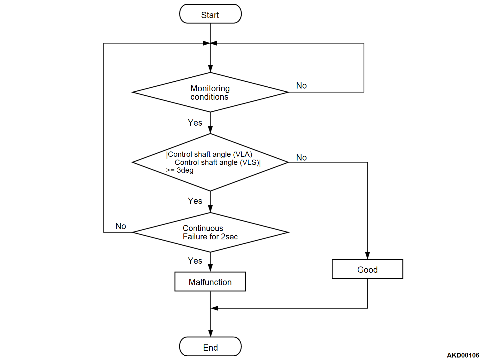
DTC SET CONDITIONS <Range/Performance problem - correlation>
Check Condition
- More than 0.2 seconds have passed since the engine starting sequence was completed.
Judgment Criterion
- The difference between the virtual control angle and the actual control angle, which is calculated from the variable valve lift sensor output signal, exceeds 3°.
| note | Virtual control angle: The value which the valve lift ECU has calculated in accordance with the variable valve lift sensor output signal (the ECM communicates via VLC-CAN). |
| note | Actual control angle: The value calculated from the variable valve lift sensor output |
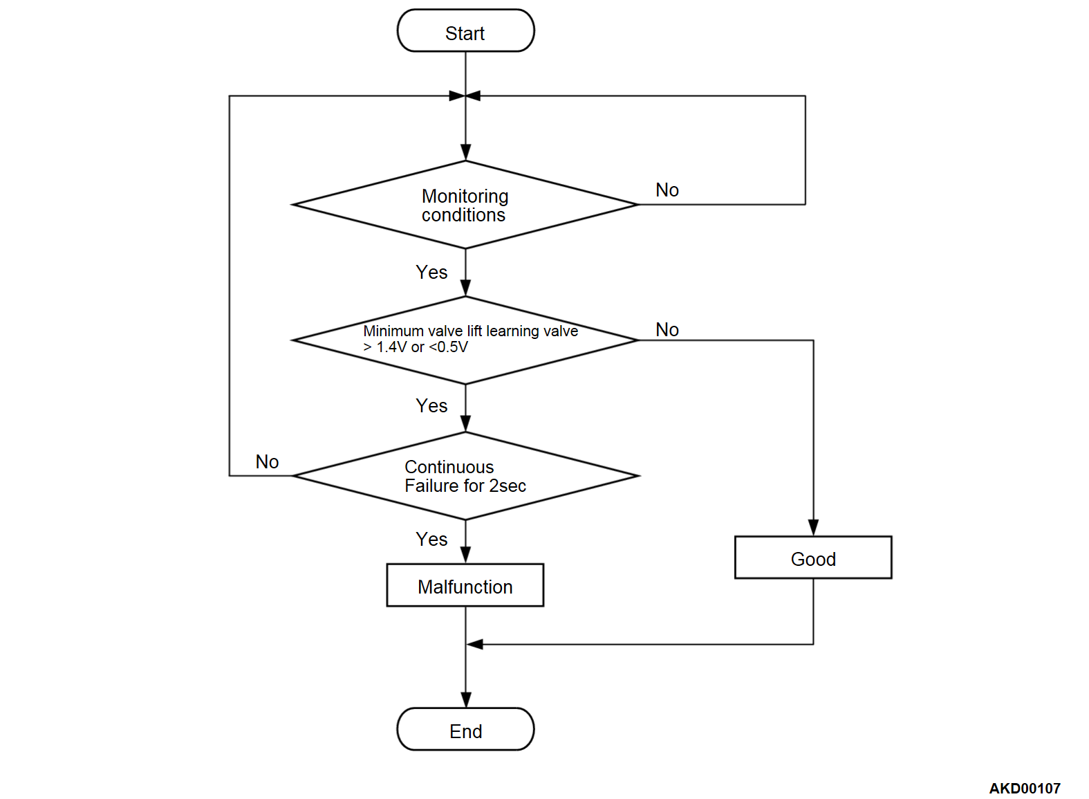
DTC SET CONDITIONS <Range/Performance problem>
Check Condition
- More than 0.2 seconds have passed since the engine starting sequence was completed.
Judgment Criterion
- The minimum valve lift learning value is less than 0.5 volt.
or
- The minimum valve lift learning value is higher than 1.4 volts.
FAIL-SAFE AND BACKUP FUNCTION
- The valve lift is fixed to maximum. Otherwise, deenergizes the motor.
- V.V.T. phase angle is set to most retarded position.
TROUBLESHOOTING HINTS (The most likely causes for this code to be stored are: )
- Variable valve lift sensor circuit harness damage, or connector damage.
- The variable valve lift sensor improperly installed
- Variable valve lift sensor failed.
- Defective variable valve lift system.
- Valve lift ECU failed.
- ECM failed.
DIAGNOSIS
STEP 1. Check whether the variable valve lift sensor is installed properly.
STEP 2. Check of harness damage in VLS5 line between ECM connector and variable valve lift sensor connector.
Is the harness wire in good condition?
STEP 3. Check of open circuit and harness damage in VLSE line between ECM connector and variable valve lift sensor connector.
Is the harness wire in good condition?
STEP 4. Check of harness damage in VLS line between ECM connector and variable valve lift sensor connector.
Is the harness wire in good condition?
STEP 5. Variable valve lift mechanism check
Refer to GROUP 11A, On-vehicle Service - Variable Valve Lift Mechanism Check  .
.
 .
. Is the check result normal?
![[Previous]](../../../buttons/fprev.png)
![[Next]](../../../buttons/fnext.png)


