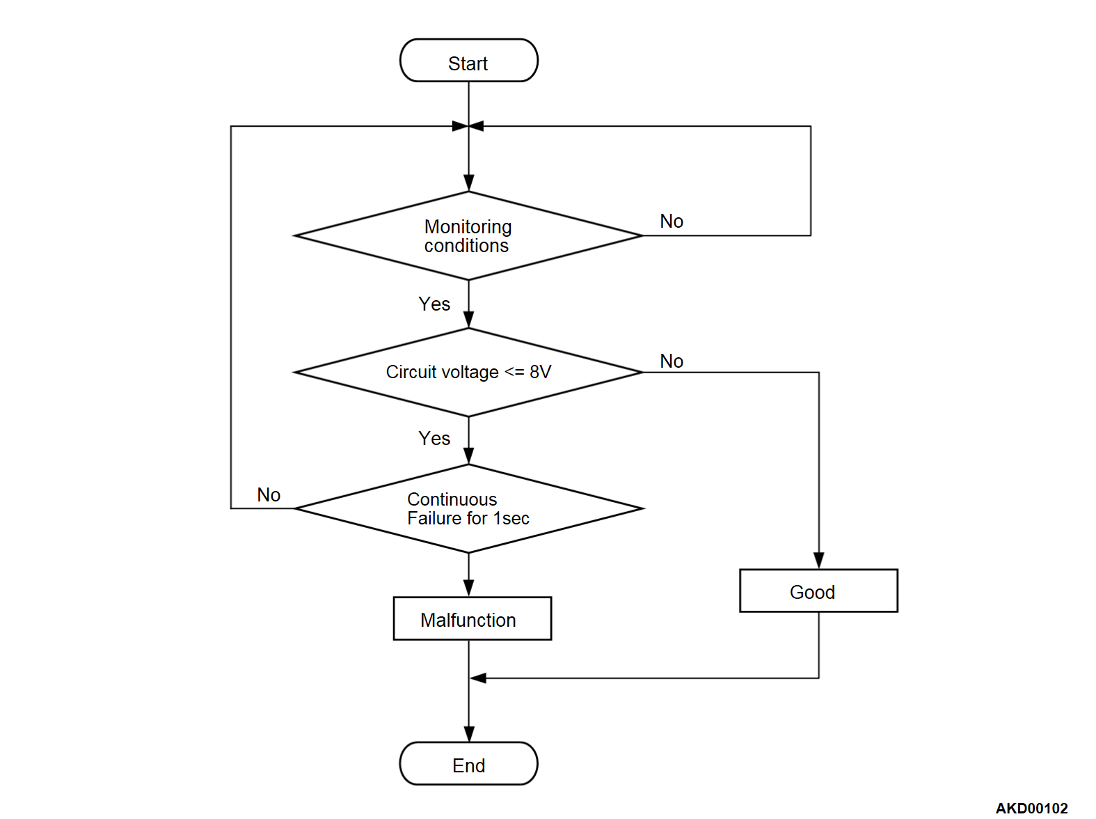
DTC P1041: Variable Valve Lift Control Motor Supply Voltage Circuit Low
CIRCUIT OPERATION
- Battery positive voltage is applied to the variable valve lift control relay.
- ECM terminal VLCR applies current to the variable valve lift control relay coil by turning ON the power transistor in the unit in order to turn the relay ON.
- When the variable valve lift control relay turns ON, battery positive voltage is supplied by the variable valve lift control relay to the valve lift ECU terminal BATM.
TECHNICAL DESCRIPTION
- If the ECM receives ignition switch ON signal through the ETACS-ECU, the ECM will turn on the variable valve lift control relay. This will allow power supply from the variable valve lift control motor to be delivered to the valve lift ECU.
MONITOR EXECUTION
- Continuous
MONITOR EXECUTION CONDITIONS (Other monitor and Sensor)
Other Monitor (There is no temporary DTC stored in memory for the item monitored below)
- Variable valve lift system monitor
Sensor (The sensor below is determined to be normal)
- Not applicable
DTC SET CONDITIONS
Check Condition
- More than 2 seconds have passed since the engine starting sequence was completed.
Judgment Criterion
- The ECM has received malfunction from the valve lift ECU via CAN.
- Contents of malfunction which the valve lift ECU detects
- Power supply voltage for activating the variable valve lift control motor is 8 volts or less
FAIL-SAFE AND BACKUP FUNCTION
- Deenergizes the variable valve lift control motor.
TROUBLESHOOTING HINTS (The most likely causes for this code to be stored are: )
- Variable valve lift control relay failed.
- Open or shorted variable valve lift control relay circuit, harness damage, or connector damage.
- Open valve lift ECU ground circuit, harness damage, or connector damage.
- Valve lift ECU failed.
- ECM failed.
DIAGNOSIS
STEP 1. Check the variable valve lift control relay.
STEP 2. Check the continuity at valve lift ECU harness side connector.
(1) Disconnect the valve lift ECU connector and measure at the harness side.
(2) Measure the continuity between terminal GND and ground.
- Continuity (2 ohms or less)
Does continuity exist?
STEP 3. Measure the power supply voltage at variable valve lift control relay harness side connector
(1) Disconnect the variable valve lift control relay connector and measure at the harness side.
(2) Measure the voltage between terminal power supply line and ground.
- Voltage should be battery positive voltage.
Is battery positive voltage (approximately 12 volts) present?
STEP 4. Measure the power supply voltage at ECM harness side connector.
(1) Disconnect the ECM connector and measure at the harness side.
(2) Measure the voltage between terminal VLCR and ground.
- Voltage should be battery positive voltage.
Is battery positive voltage (approximately 12 volts) present?
STEP 5. Measure the power supply voltage at valve lift ECU harness side connector.
(1) Disconnect the valve lift ECU connector and measure at the harness side.
(2) Short-circuit the terminal VLCR of the ECM harness connector to the ground.
(3) Measure the voltage between terminal BATM and ground.
- Voltage should be battery positive voltage.
Is battery positive voltage (approximately 12 volts) present?
STEP 6. Check of short to ground and open circuit in BATM line between variable valve lift control relay connector and valve lift ECU connector.
Is the harness wire in good condition?
STEP 7. Check of harness damage in VLCR line between variable valve lift control relay connector and ECM connector.
Is the harness wire in good condition?
STEP 8. Check of harness damage in BATM line between variable valve lift control relay connector and valve lift ECU connector.
Is the harness wire in good condition?
STEP 9. Check of harness damage in power supply line between battery and variable valve lift control relay connector.
Is the harness wire in good condition?
STEP 10. Measure the power supply voltage at ECM connector by using power plant ECU check harness special tool MB992110.
(1) Disconnect all ECM connectors. Connect the power plant ECU check harness special tool MB992110 between the separated connectors.
(2) Measure the voltage between terminal VLCR and ground.
- When the ignition switch to the "LOCK" (OFF) position, voltage should be battery positive voltage.
- When the ignition switch to the "ON" position, voltage should be 1.0 volt or lower.
Is the measured voltage normal?
STEP 11. Check the trouble symptoms.
(1) Carry out test drive with the drive cycle pattern. Refer to Diagnostic Function - OBD-II Drive Cycle - Pattern 23  .
.
 .
.(2) Check the diagnostic trouble code (DTC).
Is DTC P1041 stored?
![[Previous]](../../../buttons/fprev.png)
![[Next]](../../../buttons/fnext.png)


