DTC P2859: Auxiliary Gearbox Gear 1 Incorrect Ratio
DIAGNOSTIC FUNCTION
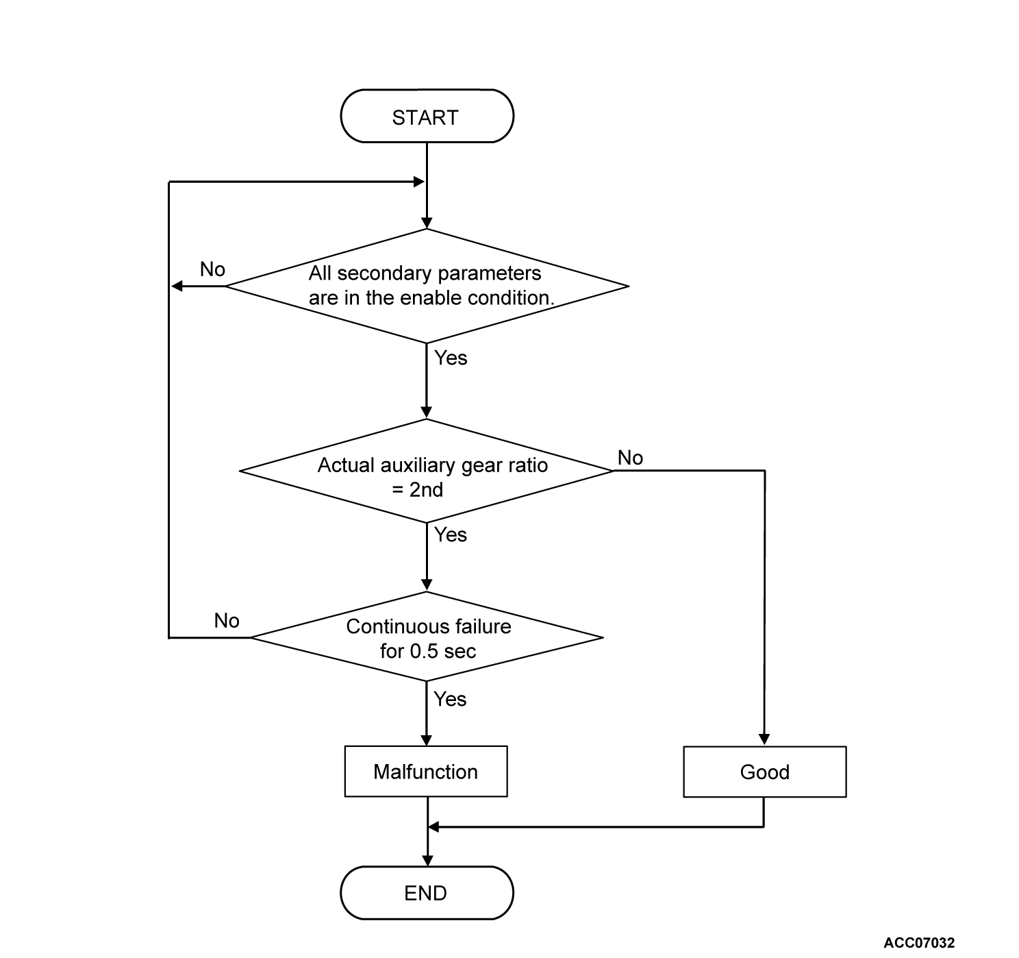
The TCM determines that the system is faulty when the auxiliary gearbox remains the gear ratio is abnormal although the TCM commands the 1st gear.
DESCRIPTIONS OF MONITOR METHODS
- The system determines that a fault has occurred when the gear ratio is within ± 10 percent of the 2nd gear ratio (0.900 - 1.100) for at least 0.5 seconds while the TCM is shifting the auxiliary gear to 1st gear.
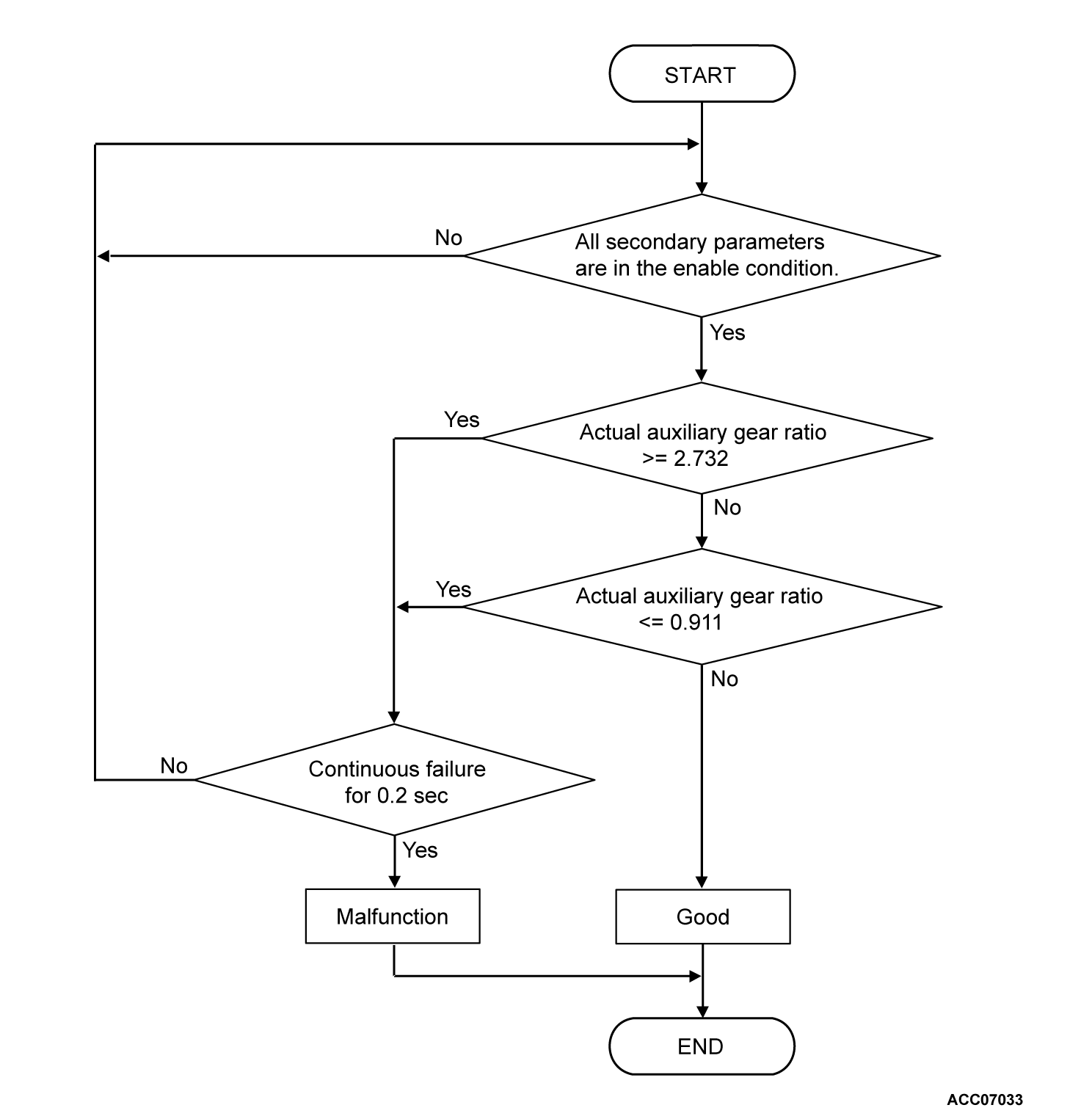
- The system determines that a fault has occurred when the gear ratio is 0.911 or less, or 2.732 or more for at least 0.2 seconds while the TCM is shifting the auxiliary gear to 1st gear.
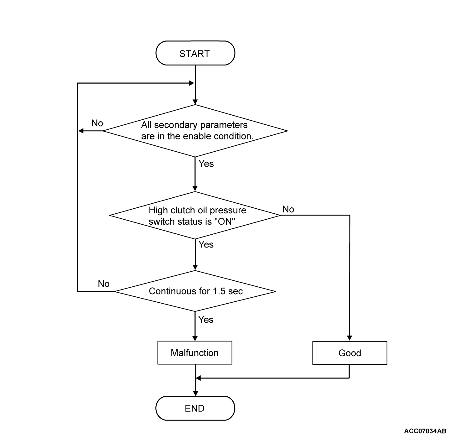
- If the high clutch pressure switch remains on for at least 1.5 seconds while the TCM is shifting the auxiliary gear to 1st gear, the system determines that a fault has occurred.
MONITOR EXECUTION
- Accelerator pedal opening angle: 7.8 percent or more <Only when determining whether 2nd gear ratio is satisfied>
- Vehicle speed: 10 km/h (6 mph) or more <Only when determining whether 1st gear ratio is not satisfied>
- Vehicle speed: 10 km/h (6 mph) or less <Only when the system monitors the high clutch pressure switch>
- Engine speed: 450 r/min or more
- Output shaft speed: 300 r/min or more <Except when the system monitors the high clutch pressure switch>
- Secondary pulley speed: 300 r/min or more <Except when the system monitors the high clutch pressure switch>
- Transmission range: "D" or "L"
- Acceleration: - 0.05 G or less <Only when determining whether 1st gear ratio is not satisfied>
- Target auxiliary gear position: 1st
- The target pressure for the high clutch and reverse brake solenoid valve is 0 MPa (0 psi) or less <Only when the system monitors the high clutch pressure switch>.
MONITOR EXECUTION CONDITIONS (OTHER MONITOR AND SENSOR)
Other Monitor (There is no temporary DTC stored in memory for the item monitored below)
- P0705: Malfunction of the transmission range switch
- P0715: Malfunction of primary pulley speed sensor
- P0720: Malfunction of the output speed sensor
- P0791: Malfunction of the secondary pulley speed sensor
- P0876: Malfunction of the high clutch pressure switch
- P0973, P0974: Malfunction of the low brake solenoid valve
- P0976, P0977: Malfunction of the high clutch and reverse brake solenoid valve
- P2857: 1st gear neutral malfunction
- P2858: 2nd gear neutral malfunction
- P285A: 2nd gear ratio malfunction
- U0001: Malfunction of CAN communication
- U0100: CAN time-out error (engine)
Sensor (The sensor below is determined to be normal)
- Transmission range switch
- Primary pulley speed sensor
- Output speed sensor
- Secondary pulley speed sensor
- Low brake solenoid valve
- High clutch and reverse brake solenoid valve
DTC SET CONDITIONS
Check Conditions
- Target auxiliary gear position: 1st
- Voltage of battery: 10 volts or more.
- Voltage of battery: 16.5 volts or less.
- Transmission range: "D" or "L"
- Accelerator pedal position sensor (main) output voltage: 1.23 volts or more
- Engine speed: 450 r/min or more
- Output speed: 300 r/min or more
- Secondary pulley speed: 300 r/min or more
Judgment Criteria
- The actual gear ratio of the auxiliary gearbox deviates by ± 10 percent or less from the 2nd gear ratio (0.900 - 1.100) for 0.5 seconds.
DTC SET CONDITIONS
Check Conditions
- Target auxiliary gear position: 1st
- Voltage of battery: 10 volts or more.
- Voltage of battery: 16.5 volts or less.
- Transmission range: "D" or "L"
- Vehicle speed: 10 km/h (6 mph) or more
- Engine speed: 450 r/min or more
- Output speed: 300 r/min or more
- Secondary pulley speed: 300 r/min or more
- Acceleration: -0.05 G or less
Judgment Criteria
- The actual gear ratio of the auxiliary gearbox deviates by ± 50 percent or more from the 1st gear ratio (0.911 or less, 2.732 or more) for 0.2 seconds.
DTC SET CONDITIONS
Check Conditions
- Target auxiliary gear position: 1st
- The target pressure for the high clutch and reverse brake solenoid valve is 0 MPa (0 psi) or less.
- Transmission range: "D" or "L"
- Vehicle speed: 10 km/h (6 mph) or less
- Engine speed: 450 r/min or more
Judgment Criteria
- The high clutch oil pressure switch is ON for 1.5 seconds.
OBD-II DRIVE CYCLE PATTERN
Accelerate to 50 km/h (31.1 mph) slowly and then stop the vehicle for at least 5 seconds with the accelerator opening angle at 10 percent or more.
PROBABLE CAUSES
- Malfunction of the valve body assembly (Faulty high clutch and reverse brake solenoid valve)
- Malfunction of the transaxle assembly
DIAGNOSIS
STEP 1. Check the following connector.
- CVT assembly connector
Check the terminals for a contact status problem and internal short circuit.
Is the check result normal?
 Repair the faulty connector.
STEP 2. Measure the output wave pattern of the high clutch and reverse brake solenoid valve at TCM connector (HRLS terminal).
(1) Connect the CVT assembly connector.
(2) Transmission range: "D" range
(3) Drive at a constant speed of approximately 20 km/h (12.4 mph) (auxiliary gearbox: at 1st gear).
(4) Connect an oscilloscope, and measure the voltage between TCM connector HRLS terminal and body ground.
Is the check result normal?
STEP 3. Symptom recheck after erasing DTC.
(1) Erase the DTC.
(2) Turn the ignition switch to the "LOCK" (OFF) position, and then wait for one minute. Then drive the vehicle until the engine has been warmed up.
(3) Check if the DTC is stored.
Is the DTC stored?
![[Previous]](../../../buttons/fprev.png)
![[Next]](../../../buttons/fnext.png)


