REMOVAL AND INSTALLATION
| caution | When the valve body assembly is replaced, initialize the CVT learned value (refer to  ). ). |
Pre-removal operation | Post-installation operation |
REMOVAL SERVICE POINTS
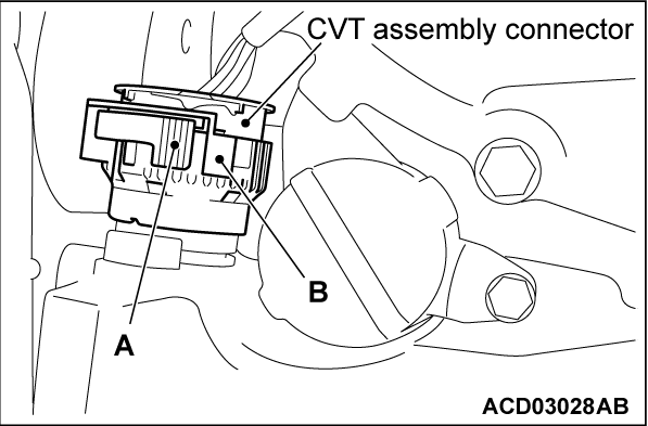
<<A>> DISCONNECTING THE CVT ASSEMBLY CONNECTOR
While pushing the part A shown in the figure, and turn the part B counterclockwise to disconnect the CVT assembly connector.
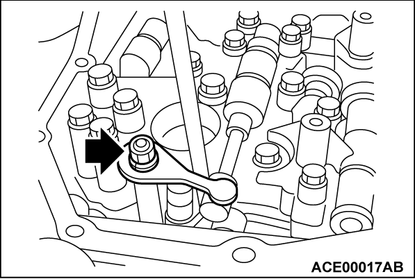
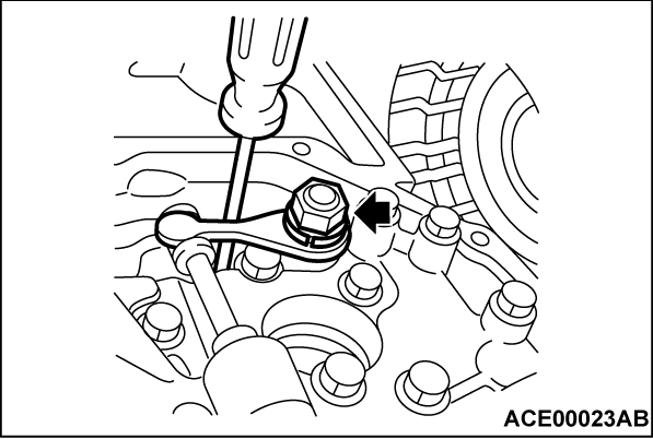
<<B>> MANUAL PLATE REMOVAL
| caution |
|
Remove the manual plate mounting nuts, and remove the manual plate and the spring washer from the manual shaft.
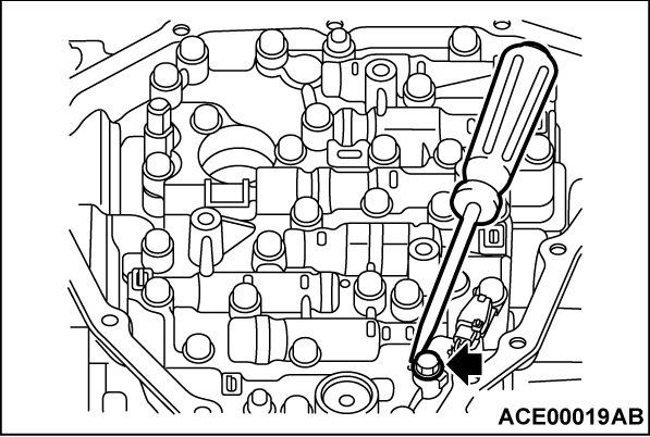
<<C>> VALVE BODY ASSEMBLY REMOVAL
| caution |
|
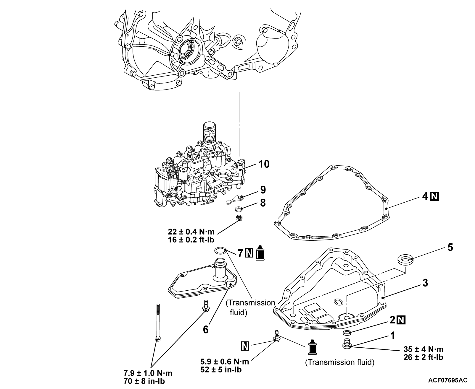
Remove the valve body assembly mounting bolts, and remove the valve body assembly.
INSTALLATION SERVICE POINTS
>>A<< VALVE BODY ASSEMBLY INSTALLATION
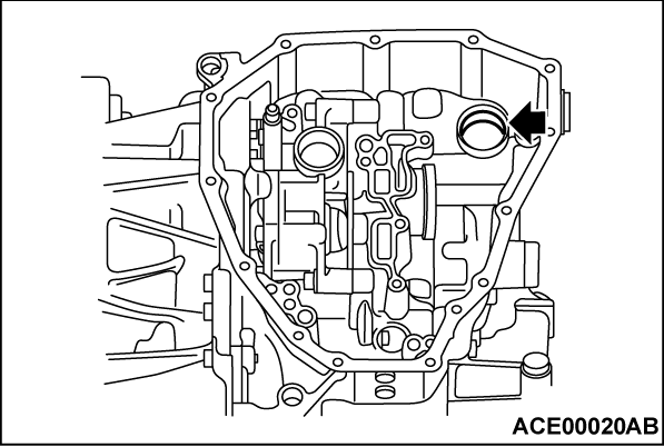
Install the valve body assembly to the transaxle assembly according to the procedure below:
1. Apply the transmission fluid to the terminal assembly mount on the transaxle assembly.
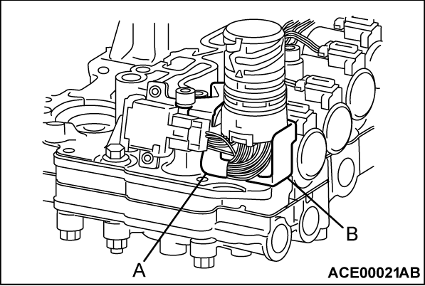
2.
The wire (A) on the valve body assembly should not be trapped in the valve body assembly bracket (B).
| caution | When the wire(s) on the valve body assembly are pinched, loose or twisted, correct them. |
3.
| caution |
|
Install the valve body assembly to the transaxle assembly.
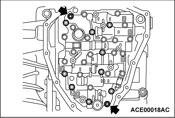
4. Tighten the two bolts by hand.
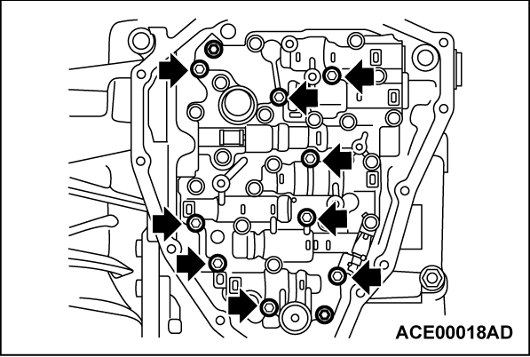
5. Then tighten nine mounting bolts by hand.
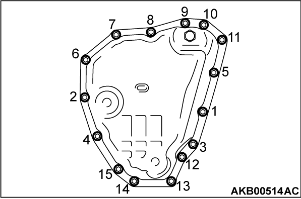
6. Tighten 11 bolts to the specified torque.
Tightening torque:
7.9 ± 1.0 N·m (70 ± 8 in-lb)
>>B<< MANUAL PLATE INSTALLATION
| caution |
|
Install the manual plate and the spring washer, and tighten the mounting nuts to the specified torque.
Tightening torque:
22 ± 0.4 N·m (16 ± 0.2 ft-lb)
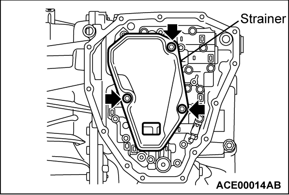
>>C<< FLUID STRAINER INSTALLATION
| caution | It should butt tight to the valve body. |
Install the fluid strainer, and then tighten the mounting bolts to the specified torque.
Tightening torque:
7.9 ± 1.0 N·m (70 ± 8 in-lb)
![[Previous]](../../../buttons/fprev.png)
![[Next]](../../../buttons/fnext.png)
