REMOVAL AND INSTALLATION
Pre-removal Operation | Post-installation Operation |
REMOVAL SERVICE POINTS
<<A>> DRIVE BELT REMOVAL
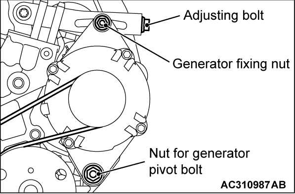
1. Loosen the nut for generator pivot bolt and generator fixing nut.
2.
| caution | To reuse the drive belt, draw an arrow indicating the rotating direction (clockwise) on the back of the belt using chalk, etc. |
Turn the adjusting bolt in the counterclockwise direction (to the left) to remove the drive belt.
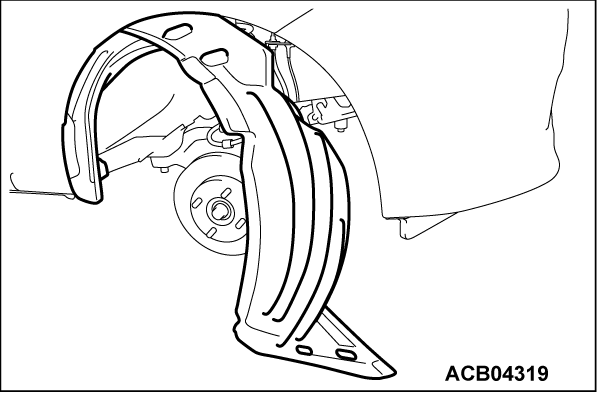
<<B>> FRONT WHEELHOUSE SPLASH SHIELD REMOVAL
Remove the securing clips on the vehicle front side to create sufficient clearance for the removal and installation of the crankshaft pulley.
<<C>> A/C COMPRESSOR SUCTION HOSE CLAMP REMOVAL
Disconnect the clamp of the A/C compressor suction hose from the side member to create sufficient clearance for the removal and installation of the crankshaft pulley center bolt.
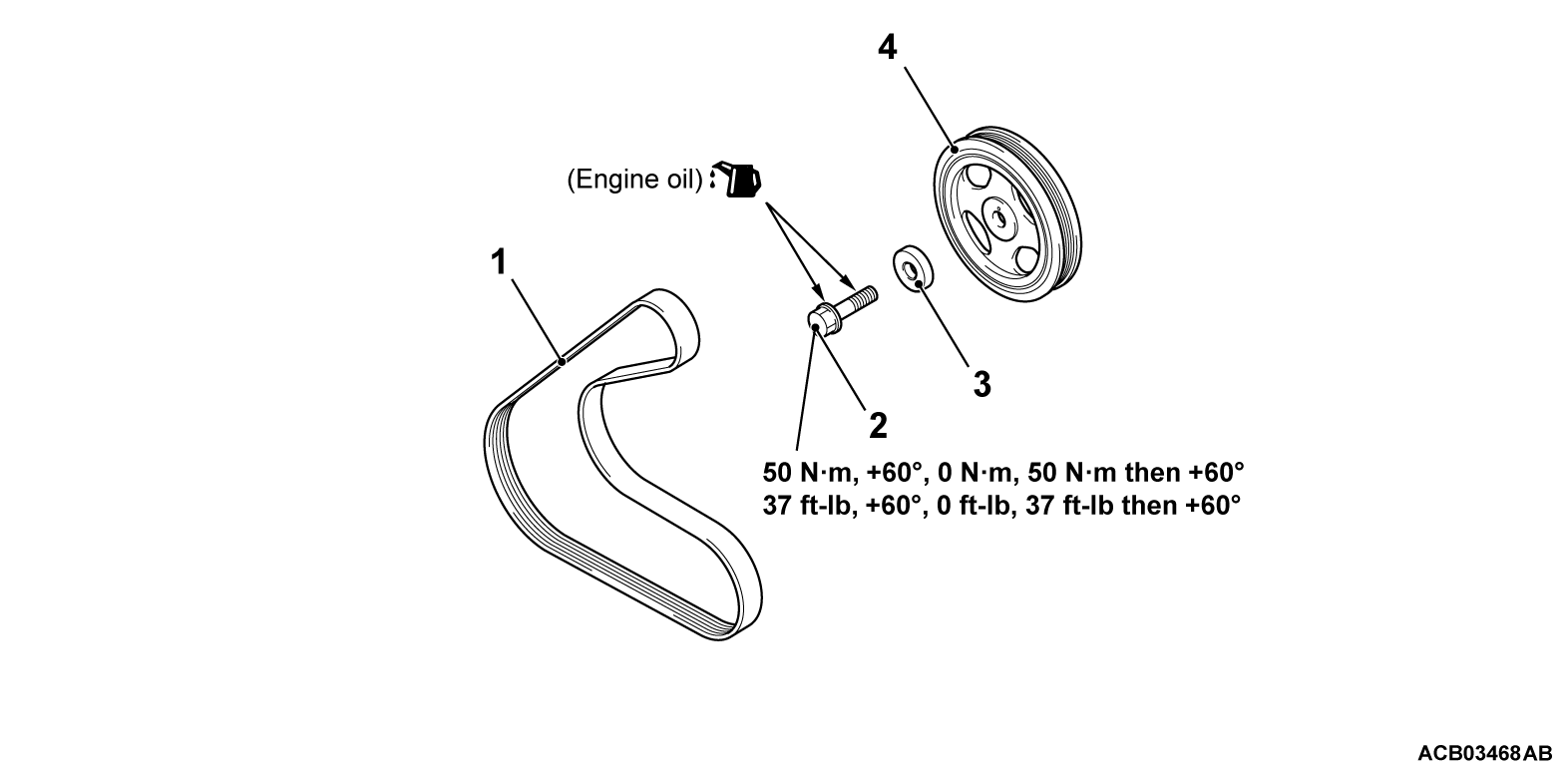
<<D>> CRANKSHAFT PULLEY CENTER BOLT/CRANKSHAFT PULLEY WASHER/CRANKSHAFT PULLEY REMOVAL
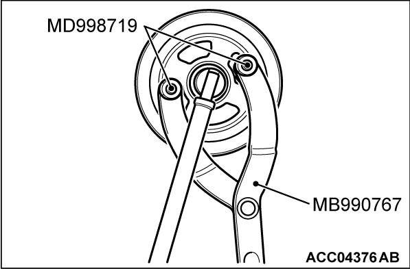
1. Use the following special tools to support the crankshaft pulley.
- Front hub and flange yoke holder (MB990767)
- Pin (MD998719)
2. Loosen the crankshaft pulley center bolt and remove the crankshaft pulley washer and crankshaft pulley.
INSTALLATION SERVICE POINT
>>A<< CRANKSHAFT PULLEY/CRANKSHAFT PULLEY WASHER/CRANKSHAFT PULLEY CENTER BOLT INSTALLATION
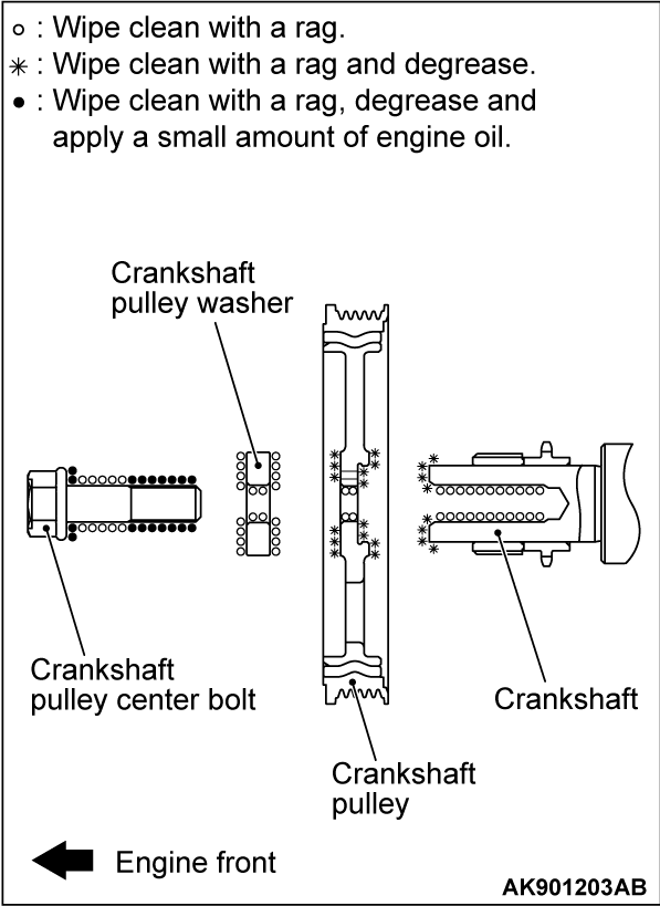
1. Using a rag, wipe dirt on the crankshaft thread hole and the crankshaft pulley washer.
2. Using a rag, wipe dirt on the crankshaft pulley and then degrease the place specified in the illustration.
| note | Perform degreasing to prevent the friction resistance from decreasing in the compressed area due to the residual oil. |
3. Install the crankshaft pulley.
4. Apply the minimum amount of engine oil to the crankshaft bolt threads and the seating surface.
5. Use the following special tools as during removal to support the crankshaft pulley.
- Front hub and flange yoke holder (MB990767)
- Pin (MD998719)
6. Tighten the crankshaft pulley center bolt to the specified torque.
Tightening torque: 50 N·m (37 ft-lb)
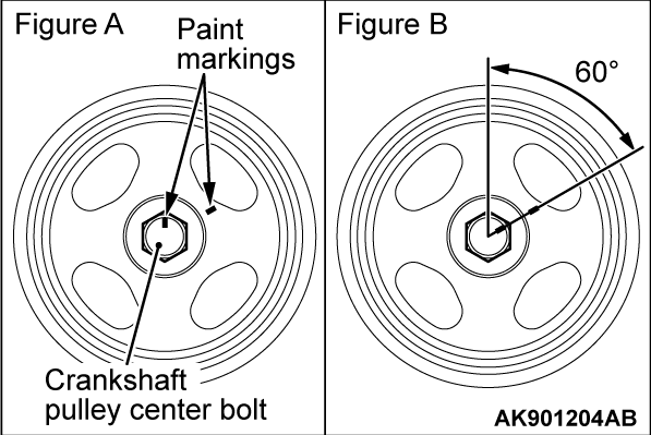
7. As shown in figure A, put a paint mark on one angle of the crankshaft pulley center bolt. Then, put a paint mark on the crankshaft pulley on the extended line of the angle next to the marked angle.
8.
| caution |
|
Tighten the crankshaft pulley center bolt in a 60°, and check that the paint mark on the crankshaft pulley center bolt aligns with the paint mark on the crankshaft pulley as shown in figure B.
9. Loosen the crankshaft pulley center bolt completely after steps 6 to 8, and then repeat steps 6 to 8.
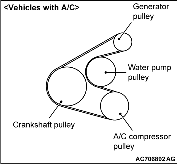
>>B<< DRIVE BELT INSTALLATION
| caution |
|
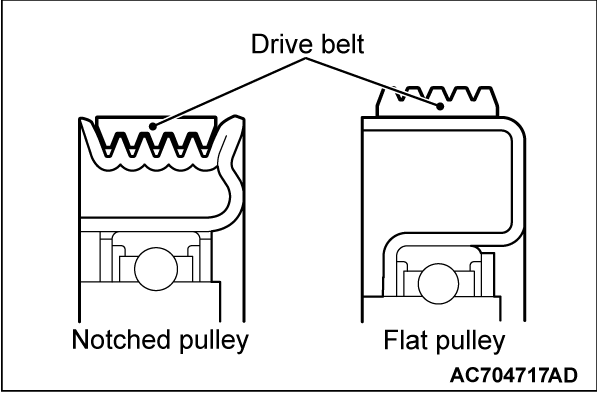
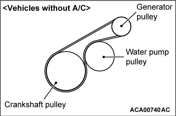
Install the drive belt to each pulley as shown in the figure.
![[Previous]](../../../buttons/fprev.png)
![[Next]](../../../buttons/fnext.png)

