P1C0A-1C Ambient Temp Sensor Rationality correlation Fault
| caution | Before replacing the ECU, ensure that the CAN bus lines is normal. |
DESCRIPTIONS OF MONITOR METHODS
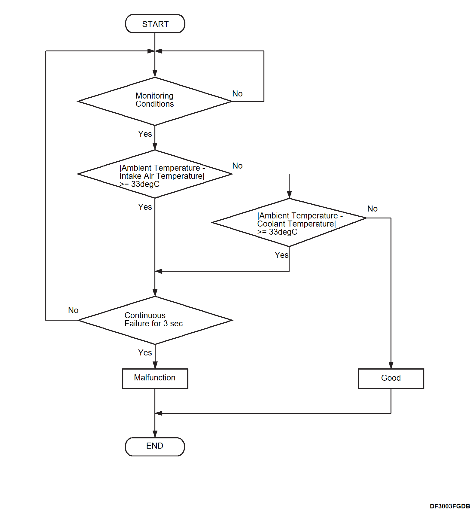
- Ambient temperature sensor is compared to Intake air sensor and Coolant temperature sensor.
- Intake air sensor and Coolant temperature sensor are selected for comparison because they should be equal to Ambient temperature after more than 6 hour soak from last drive trip.
- During driving, the difference between temperature sensor signals may become large.
Therefore, this monitor will execute within 10 second after IGN ON.
MONITOR EXECUTION
Continuous
MONITOR EXECUTION CONDITIONS (Other monitor and Sensor)
Other Monitor (There is no temporary DTC stored in memory for the item monitored below)
- Not applicable
Sensor (The sensor below is determined to be normal)
- Not applicable
TROUBLE JUDGMENT
Check Condition
- The heater PHEV A/C amp. power supply voltage is between 10 and 16 volts.
- Within 10 seconds after the IGN power supply is turned to ON from OFF.
- Comparison monitor for water temperature and intake air temperature: Normal
note The comparison monitor for water temperature and intake air temperature is performed when the IGN power supply is turned ON after 6 hours passes from when the IGN power supply is turned OFF. - Battery inlet refrigerant temperature 4°C (39.2°F) or more
- Drive battery temperature minimum value 15°C (59°F) or more
- Engine intake air temperature 15°C (59°F) or more
Judgment Criterion
- The absolute value of the difference between the ambient temperature and the intake air temperature| remains 33°C or less for 3 seconds.
- The absolute value of the difference between the ambient temperature and the coolant temperature remains 33°C or less for 3 seconds.
OBD-II DRIVE CYCLE PATTERN
- Refer to OBD-II Drive Cycle – Pattern 2 OBD-II DRIVE CYCLE
 .
.
PROBABLE CAUSES
- Malfunction of harness and connectors
- Malfunction of ambient sensor (for PHEV A/C amp.)
- Malfunction of PHEV A/C amp.
DIAGNOSIS PROCEDURE
2.Check of open circuit in SG line between PHEV A/C amp. and ambient sensor (for PHEV A/C amp.) sensor
3.Voltage measurement at ambient sensor (for PHEV A/C amp.) connector (terminal No. 2)
(1) Disconnect the connector, and measure at the wiring harness side.
(2) Change the power supply mode of the electric motor switch to ON (READY indicator: ON).
(3) Measure the voltage between the ambient sensor (for PHEV A/C amp.) connector (terminal No. 2) and body ground.
OK : About 5 V
Is the inspection result normal?
4.Voltage measurement at PHEV A/C amp. connector (T_AMB terminal)
(1) Disconnect the connector, and measure at the wiring harness side.
(2) Change the power supply mode of the electric motor switch to ON (READY indicator: ON).
(3) Measure the voltage between the PHEV A/C amp. connector (T_AMB terminal) and body ground.
OK : About 5 V
Is the inspection result normal?
 Repair harness or connector.
5.Check the ambient sensor (for PHEV A/C amp.)
(1) Measure the ambient temperature near the ambient sensor.
(2) Measure the resistance between the ambient sensor terminals.
(3) Check that the ambient sensor properly detects the ambient temperature using the measurement result of (1) and resistance value of (2).
Is the inspection result normal?
 Replace ambient sensor (for PHEV A/C amp.). Refer to REMOVAL AND INSTALLATION
 .
.6.Test the OBD-II drive cycle.
(1) Carry out a test drive with the drive cycle pattern. Refer to OBD-II Drive Cycle - Pattern 2 OBD-II DRIVE CYCLE .
.
 .
.(2) Check the DTC.
Is the DTC set?
 Replace PHEV A/C amp. Refer to Removal and Installation
 .
. The trouble can be an intermittent malfunction. Refer to General Information - How to Use Troubleshooting/Inspection Service Points, How to Cope with Intermittent Malfunctions HOW TO COPE WITH INTERMITTENT MALFUNCTIONS
 .
.![[Previous]](../../../buttons/fprev.png)
![[Next]](../../../buttons/fnext.png)
