DTC No. P0A1F-00 ECU Internal Failure
MONITOR EXECUTION
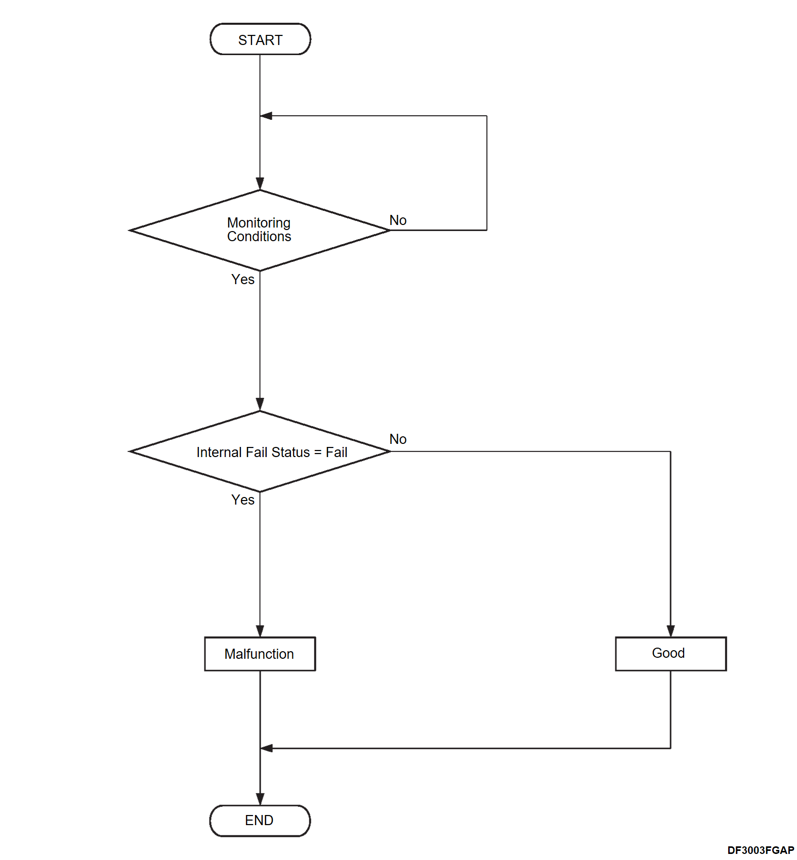
- Once per driving cycle (During the BMU termination) <Condition A>
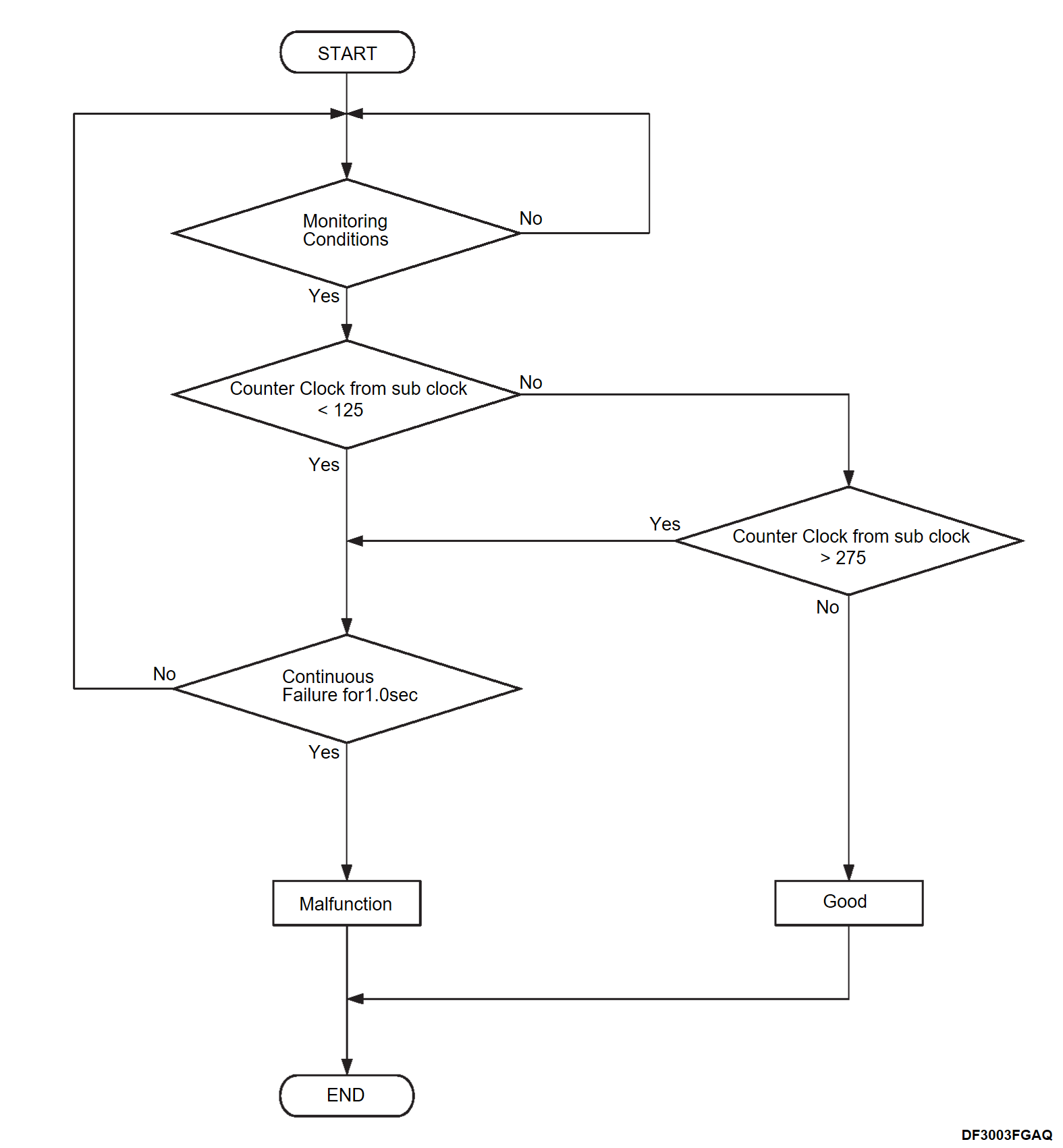
- Continuous <Condition B>
MONITOR EXECUTION CONDITIONS (Other monitor and Sensor)
Other Monitor (There is no temporary DTC set in memory for the item monitored below)
- BMU monitor
Sensor (The sensor below is determined to be normal)
- Not applicable
Check Condition A
- The BMU power supply voltage is more than 7.578 volts.
- The shutdown sequense is ON
Check Condition B
- The BMU power supply voltage is more than 7.578 volts.
Judgment Criterion A
- The fail condition of the internal fail status is detected.
Judgment Criterion B
- The counter clock from sub clock is less than 125 or more than 275 for 1 second or more.
OBD-II DRIVE CYCLE PATTERN
- Refer to OBD-II Drive Cycle OBD-II DRIVE CYCLE
 .
.
TROUBLESHOOTING HINTS
- Malfunction of the cell voltage wiring harness
- Malfunction of the BMU
- Malfunction of the drive battery (battery module No. 1 to 8)
DIAGNOSIS
Required Special Tools:
- MB992744: Vehicle communication interface-Lite (V.C.I.-Lite)
- MB992745: V.C.I.-Lite main harness A
- MB992747: V.C.I.-Lite USB cable short
- MB992748: V.C.I.-Lite USB cable long
1.Test the OBD-II drive cycle.
(1) Carry out a test drive with the drive cycle pattern. Refer to OBD-II Drive Cycle OBD-II DRIVE CYCLE .
.
 .
.(2) Check the DTC.
Is the DTC set?
 The procedure is complete.
2.Cell voltage harness check
(1) Disassemble the drive battery (Refer to SERVICE PROCEDURE ).
).
 ).
).(2) Check the cell voltage wiring harnesses of the battery module No. 1 to No. 8 (Refer to CELL VOLTAGE HARNESS CHECK ).
).
 ).
).Is the check result normal?
 Replace the cell voltage harness (Refer to BATTERY CONTORL HARNESS AND CELL VOLTAGE HARNESS REMOVAL AND INSTALLATION
 ). Then,
3.Module check
Check the battery module No. 1 to No. 8 (Refer to BATTERY MODULE CHECK ).
). Replace the BMU (Refer to BATTERY MANAGEMENT UNIT (BMU) REMOVAL AND INSTALLATION
 ). Then,
 Replace the failed battery module (Refer to SERVICE PROCEDURE
 ). Then,
 ).
).Is the check result normal?
 Replace the BMU (Refer to BATTERY MANAGEMENT UNIT (BMU) REMOVAL AND INSTALLATION
 ). Then,
 Replace the failed battery module (Refer to SERVICE PROCEDURE
 ). Then,
4.Test the OBD-II drive cycle.
(1) Carry out a test drive with the drive cycle pattern. Refer to OBD-II Drive Cycle OBD-II DRIVE CYCLE .
.
 .
.(2) Check the DTC.
Is the DTC set?
 Retry the troubleshooting.
 The procedure is complete.
![[Previous]](../../../buttons/fprev.png)
![[Next]](../../../buttons/fnext.png)

