DTC No. P0D2E-00 PDU V1 voltage sensor Rationality-correlation
DTC No. P0D2F-00 PDU V1 voltage sensor Range check-min
DTC No. P0D30-00 PDU V1 voltage sensor Range check-max
DTC No. P0E8D-00 PDU V2M voltage sensor Rationality-correlation
DTC No. P0E8E-00 PDU V2M voltage sensor Range check-min
DTC No. P0E8F-00 PDU V2M voltage sensor Range check-max
DTC No. P3008-17 PDU V0 voltage sensor Range check-max
DTC No. P3009-16 PDU V0 voltage sensor Range check-min
DTC No. P300A-1C PDU V0 voltage sensor Rationality-correlation
DTC No. P300B-17 PDU V2S voltage sensor Range check-max
DTC No. P300C-16 PDU V2S voltage sensor Range check-min
DTC No. P300D-1C PDU V2S voltage sensor Rationality-correlation
DTC No. P300E-1C PDU V2 voltage sensor deviation malfunction
MONITOR EXECUTION
Continuous
MONITOR EXECUTION CONDITIONS (Other monitor and Sensor)
Other Monitor (There is no temporary DTC set in memory for the item monitored below)
- Not applicable
Sensor (The sensor below is determined to be normal)
- Power drive unit voltage sensor (Upper/Lower limit malfunction) <DTC No. P0D2E-00, P0E8D-00, P300A-1C, P300D-1C, P300E-1C>
DTC SET CONDITIONS
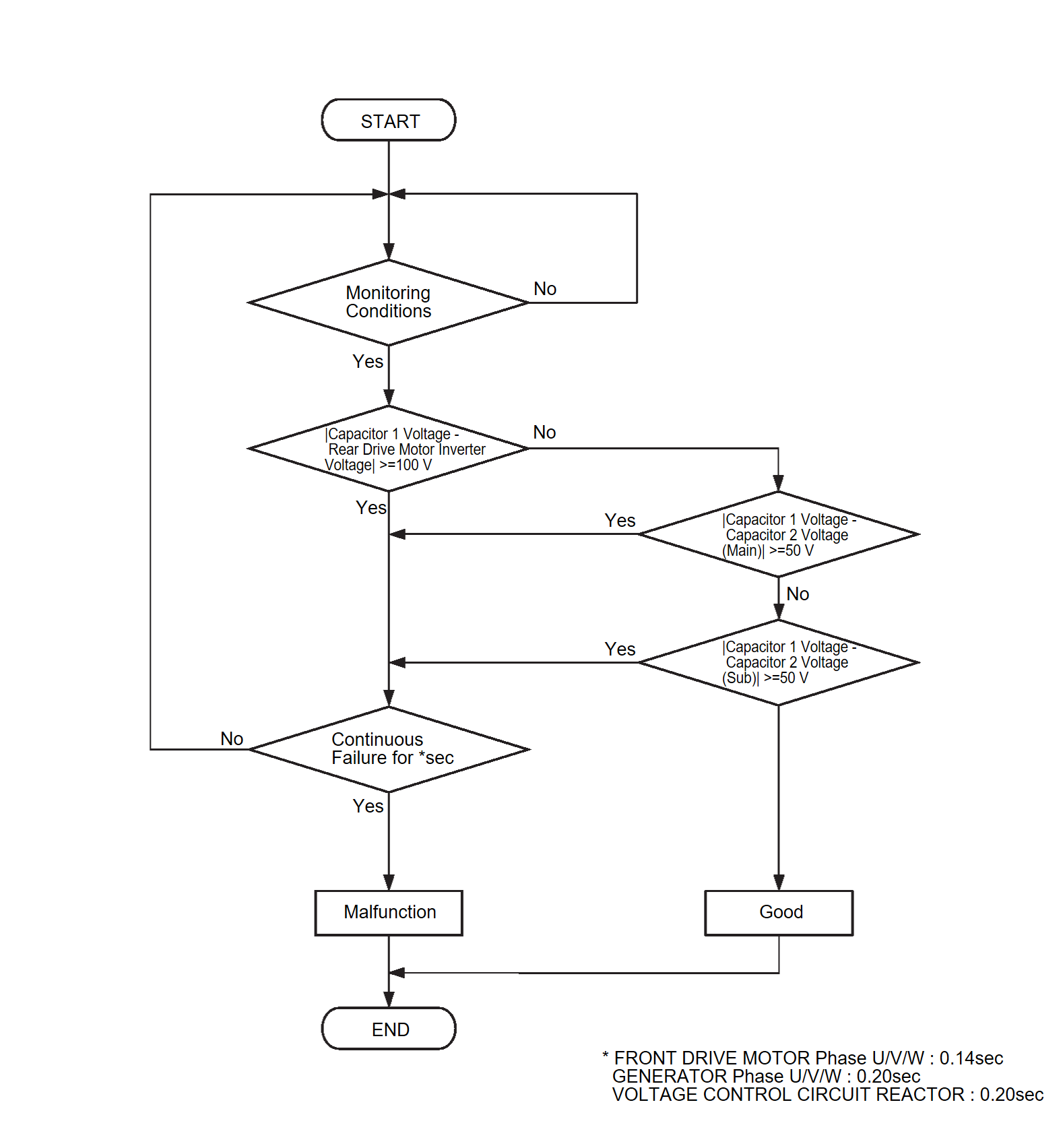
Check Condition A <DTC No. P0D2E-00>
- Power drive unit (VCU) power supply voltage is 8.0 volts or more.
- Voltage Control Mode: ON
- Time after above conditions satisfy is 0.5 second or more.
Judgment Criterion A <DTC No. P0D2E-00>
- The difference between the capacitor 1 voltage and REMCU voltage is 100 volts or more for 0.2 second or more.
- The difference between the capacitor 1 voltage and capacitor 2 voltage (Main) is 50 volts or more for 0.2 second or more.
- The difference between the capacitor 1 voltage and capacitor 2 voltage (Sub) is 50 volts or more for 0.2 second or more.
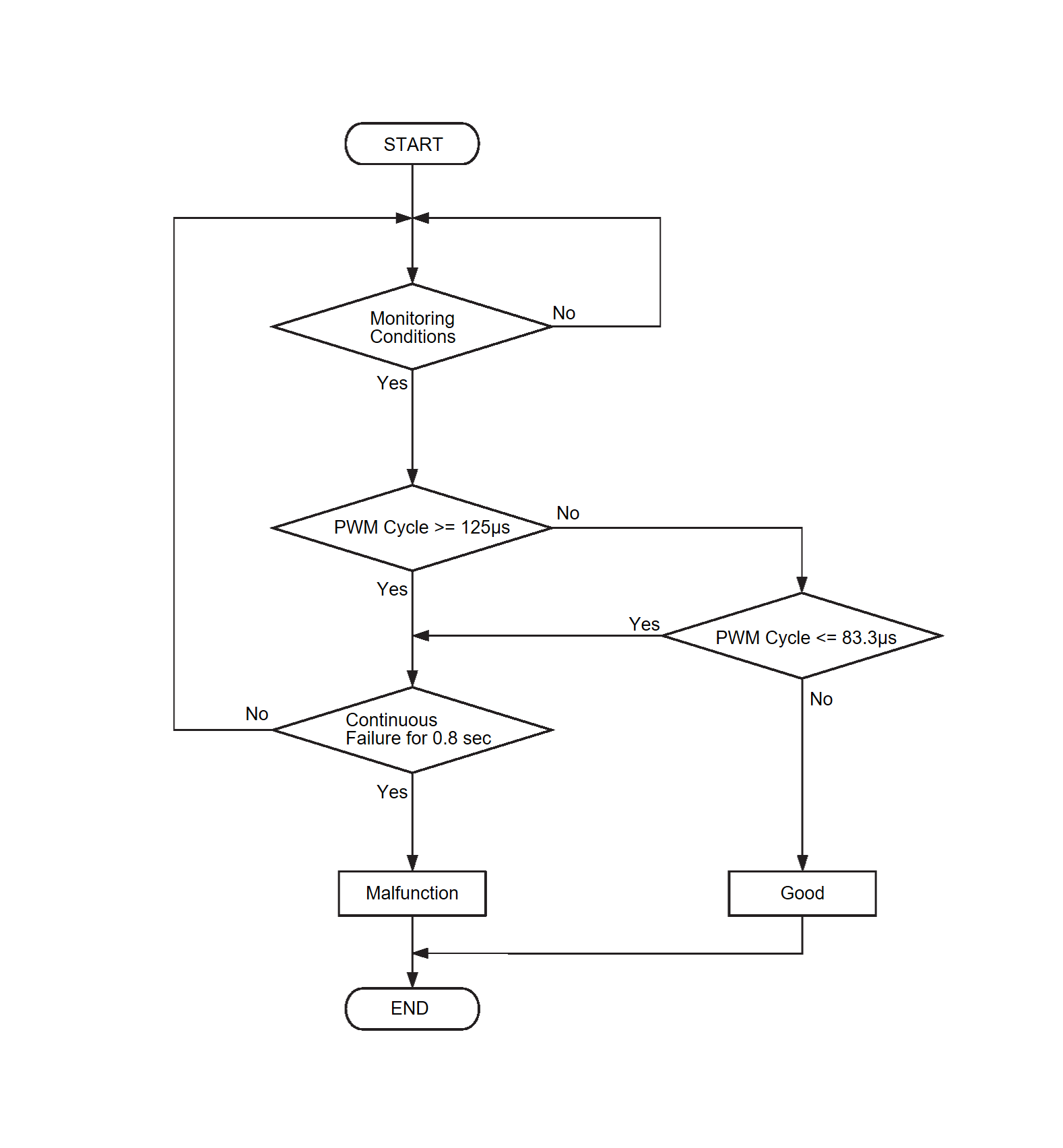
Check Condition B <DTC No. P0D2E-00>
- Power drive unit (VCU) power supply voltage is 8.0 volts or more.
Judgment Criterion B <DTC No. P0D2E-00>
- The PWM cycle is 125 microseconds or more for 0.8 second or more.
- The PWM cycle is 83.3 microseconds or more for 0.8 second or more.
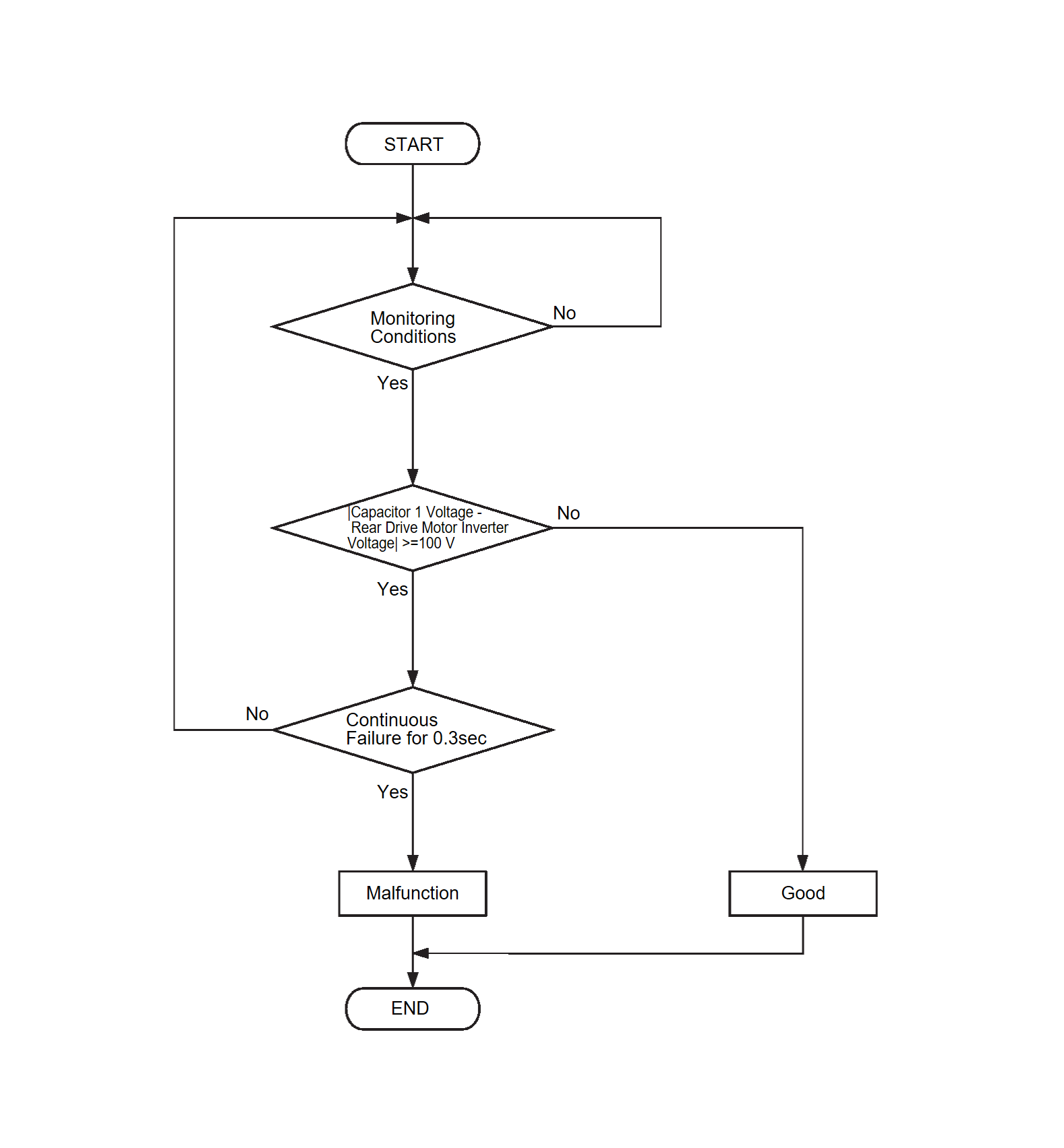
Check Condition C <DTC No. P0D2E-00>
- Power drive unit (VCU) power supply voltage is 8.0 volts or more.
Judgment Criterion C <DTC No. P0D2E-00>
- The difference between the capacitor 1 voltage and REMCU voltage is 100 volts or more for 0.3 second or more.
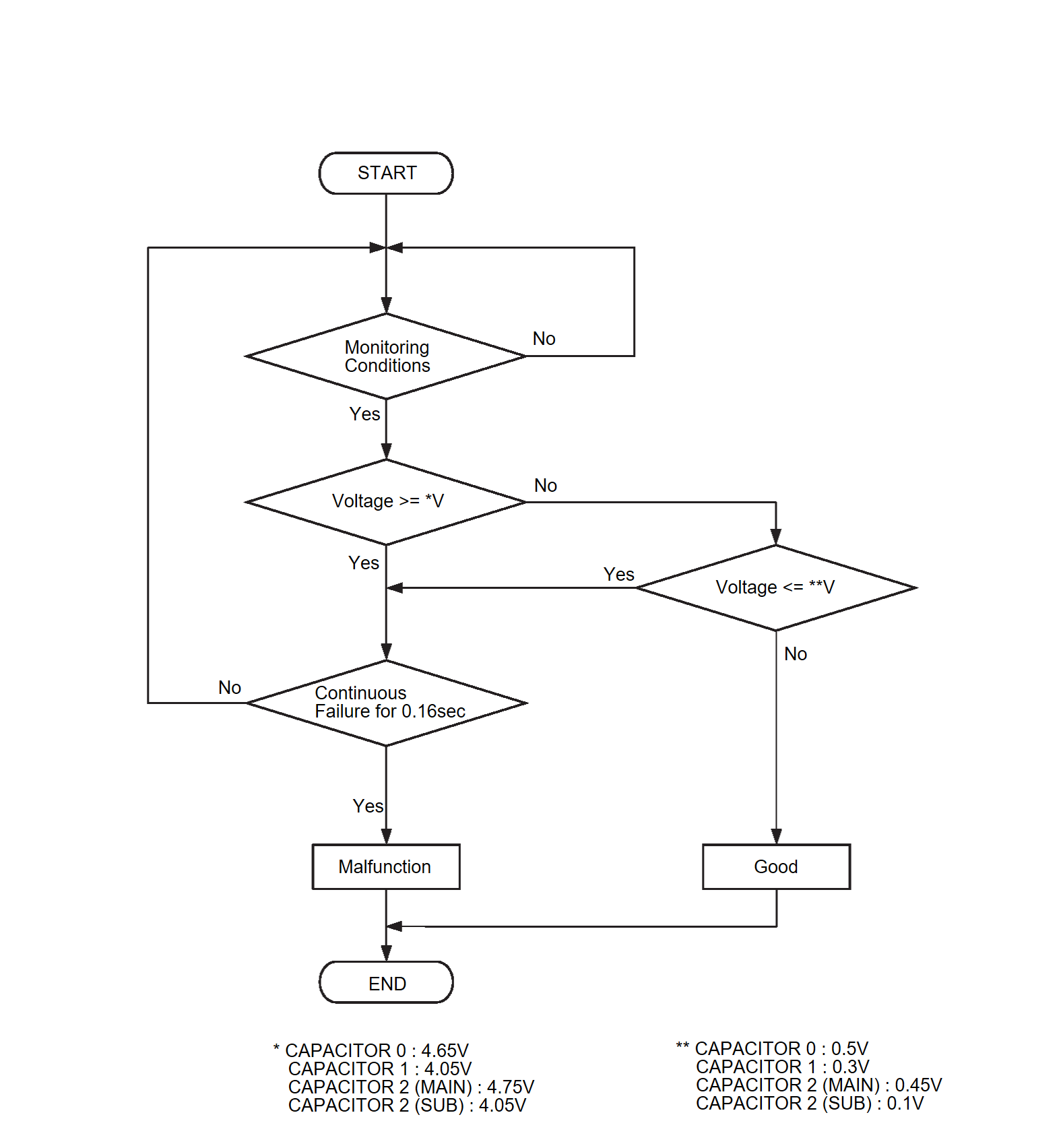
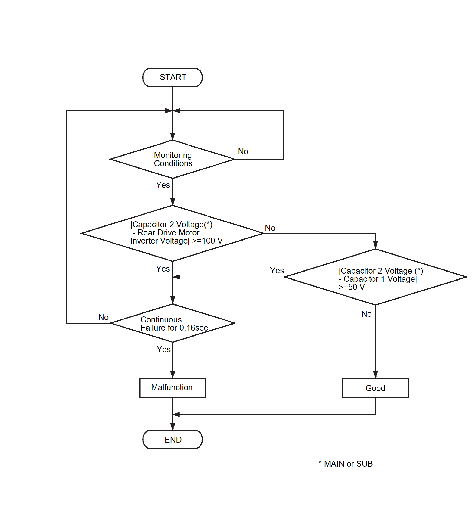
Logic Flow Chart <DTC No. P0D2F-00, P0D30-00, P0E8E-00, P0E8F-00, P3008-17, P3009-16, P300B-17, P300C-16>
Check Condition <DTC No. P0D2F-00, P0D30-00, P0E8E-00, P0E8F-00, P3008-17, P3009-16, P300B-17, P300C-16>
- Power drive unit (VCU) power supply voltage is 8.0 volts or more.
Judgment Criterion <DTC No. P0D2F-00>
- The capacitor 1 voltage is 0.3 volt or less for 0.16 second or more.
Judgment Criterion <DTC No. P0D30-00, P300B-17>
- The capacitor 1 voltage is 4.05 volts or more for 0.16 second or more. <DTC No. P0D30>
- The capacitor 2 (Sub) voltage is 4.05 volts or more for 0.16 second or more. <DTC No. P300B>
Judgment Criterion <DTC No. P0E8E-00>
- The capacitor 2 (Main) voltage is 0.45 volt or less for 0.16 second or more.
Judgment Criterion <DTC No. P0E8F-00>
- The capacitor 2 (Main) voltage is 4.75 volts or more for 0.16 second or more.
Judgment Criterion <DTC No. P3008-17>
- The capacitor 0 voltage is 4.65 volts or more for 0.16 second or more.
Judgment Criterion <DTC No. P3009-16>
- The capacitor 0 voltage is 0.5 volt or less for 0.16 second or more.
Judgment Criterion <DTC No. P300C-16>
- The capacitor 2 (Sub) voltage is 0.1 volt or less for 0.16 second or more.
Check Condition <DTC No. P0E8D-00>
- Power drive unit (VCU) power supply voltage is 8.0 volts or more.
- Voltage Control Unit (VCU): OFF
- Time after above conditions satisfy is 0.5 second or more.
Judgment Criterion <DTC No. P0E8D-00>
- The difference between the capacitor 2 (Main) voltage and REMCU voltage is 100 volts or more for 0.2 second or more.
- The difference between the capacitor 2 (Main) voltage and capacitor 1 voltage is 50 volts or more for 0.2 second or more.
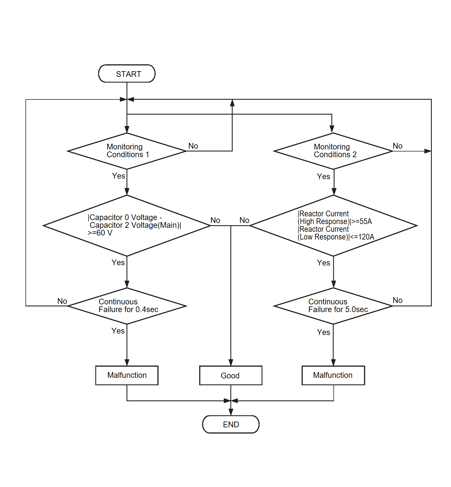
Check Condition A <DTC No. P300A-1C>
- Power drive unit (VCU) power supply voltage is 8.0 volts or more.
Check Condition B <DTC No. P300A-1C>
- Power drive unit (VCU) power supply voltage is 8.0 volts or more.
- Voltage Control Unit (VCU): ON
Judgment Criterion A <DTC No. P300A-1C>
- The difference between the capacitor 0 voltage and capacitor 2 (Main) voltage is 60 volts or more for 0.40 second or more.
Judgment Criterion B <DTC No. P300A-1C>
- The reactor current (High response) is 55 amperes or more for 5 seconds or more.
- The reactor current (Low response) is 120 amperes or more for 5 seconds or more.
Check Condition A <DTC No. P300D-1C>
- Power drive unit (VCU) power supply voltage is 8.0 volts or more.
- Voltage Control Unit (VCU): OFF
- Time after above conditions satisfy is 0.5 second or more.
Judgment Criterion A <DTC No. P300D-1C>
- The difference between the capacitor 2 (Sub) voltage and REMCU voltage is 100 volts or more for 0.2 second or more.
- The difference between the capacitor 2 (Sub) voltage and capacitor 1 voltage is 50 volts or more for 0.2 second or more.
Check Condition B <DTC No. P300D-1C>
- Power drive unit (VCU) power supply voltage is 8.0 volts or more.
Judgment Criterion B <DTC No. P300D-1C>
- The PWM cycle is 125 microseconds or more for 0.8 second or more.
- The PWM cycle is 83.3 microseconds or more for 0.8 second or more.
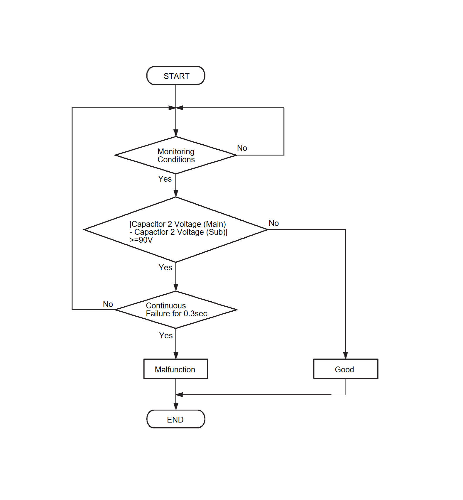
Check Condition
- Power drive unit (VCU) power supply voltage is 8.0 volts or more.
Judgment Criterion
- The difference between the capacitor 2 (Main) voltage and capacitor 2 (Sub) voltage is 90 volts or more for 0.3 second or more.
OBD-II DRIVE CYCLE PATTERN
- Refer to OBD-II Drive Cycle OBD-II DRIVE CYCLE
 .
.
TROUBLESHOOTING HINTS
- Malfunction of the power drive unit
DIAGNOSIS
Required Special Tools:
- MB992744: Vehicle communication interface-Lite (V.C.I.-Lite)
- MB992745: V.C.I.-Lite main harness A
- MB992747: V.C.I.-Lite USB cable short
- MB992748: V.C.I.-Lite USB cable long
1.M.U.T.-IIISE other DTC check
Check whether the DTC, which has the higher priority than this DTC, is set. (Refer to DTC Inspection Priority Chart ).
). Troubleshoot the set DTC (Refer to DIAGNOSTIC TROUBLE CODE CHART
 ). Then,
 ).
).Is the DTC set?
 Troubleshoot the set DTC (Refer to DIAGNOSTIC TROUBLE CODE CHART
 ). Then,
2.Test the OBD-II drive cycle.
(1) Carry out a test drive with the drive cycle pattern. Refer to OBD-II Drive Cycle OBD-II DRIVE CYCLE .
.
 .
.(2) Check the DTC.
Is the DTC set?
 Replace the power drive unit (Refer to POWER DRIVE UNIT REMOVAL AND INSTALLATION
 ). Then,
 The trouble can be an intermittent malfunction (Refer to General Information - How to Use Troubleshooting/Inspection Service Points, How to Cope with Intermittent Malfunctions HOW TO COPE WITH INTERMITTENT MALFUNCTIONS
 ).
).3.Test the OBD-II drive cycle.
(1) Carry out a test drive with the drive cycle pattern. Refer to OBD-II Drive Cycle OBD-II DRIVE CYCLE .
.
 .
.(2) Check the DTC.
Is the DTC set?
 Retry the troubleshooting.
 The procedure is complete.
![[Previous]](../../../buttons/fprev.png)
![[Next]](../../../buttons/fnext.png)
