FUEL TANK SOLENOID VALVE CHECK
Checking the Solenoid Valve Coil Resistance
1. Remove the second seat assembly (Refer to Body Interior - Seat, Removal and Installation, Second Seat Assembly, Removal and Installation Removal and Installation ).
).
 ).
).2. Remove the floor inspection lid (RH). (Refer to Body Exterior Doors, Roof & Vehicle Security - Exterior, Loose Panel Removal and InstallationREMOVAL AND INSTALLATION )
)
 )
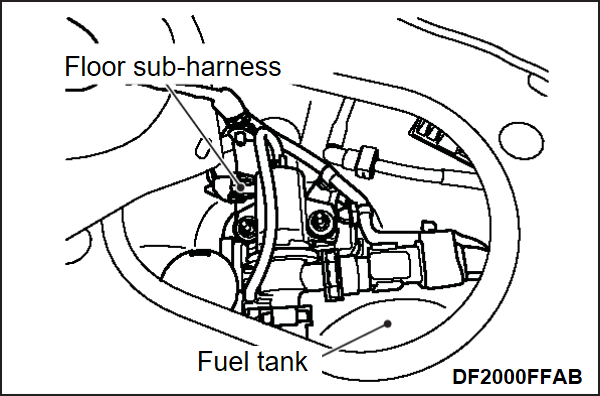
)3. Disconnect the floor sub-harness.
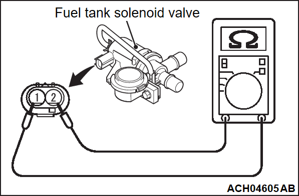
4. Measure the resistance between the terminals of the fuel tank solenoid valve.
Standard value: 25 – 30 Ω [at 20°C (68°F)]
5. Replace the fuel tank solenoid valve if resistance is out of specification.
6. Install the floor inspection lid (RH). (Refer to Body Exterior Doors, Roof & Vehicle Security - Exterior, Loose Panel Removal and InstallationREMOVAL AND INSTALLATION )
)
 )
)7. Install the second seat assembly (Refer to Body Interior - Seat, Removal and Installation, Second Seat Assembly, Removal and Installation Removal and Installation ).
).
 ).
).Checking the Solenoid Valve Operation
1. Remove the second seat assembly (Refer to Body Interior - Seat, Removal and Installation, Second Seat Assembly, Removal and Installation Removal and Installation ).
).
 ).
).2. Remove the floor inspection lid (RH). (Refer to Body Exterior Doors, Roof & Vehicle Security - Exterior, Loose Panel Removal and Installation REMOVAL AND INSTALLATION )
)
 )
)3. Disconnect the hoses from the fuel tank solenoid valve.
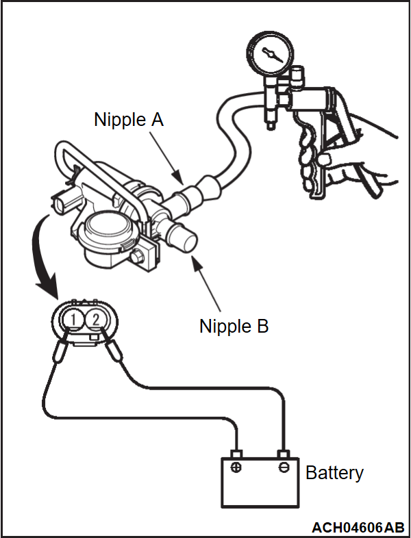
4. Connect a hand vacuum pump (pressure-application type) to nipple (A) of the fuel tank solenoid valve (refer to the illustration).
5. As described in the chart below, check airtightness by applying a pressure of approximately 25 kPa (3.62 psi) with voltage applied directly from the battery to the fuel tank solenoid valve and without applying voltage.
| Jumper wire | Nipple "B" state | Normal condition |
| Disconnected | Opened | Pressure maintained |
| Connected | Opened | Pressure leaks |
| Closed | Pressure maintained |
6. Replace the fuel tank solenoid valve if airtightness is out of specification.
7. Install the floor inspection lid (RH). (Refer to Body Exterior Doors, Roof & Vehicle Security - Exterior, Loose Panel Removal and Installation REMOVAL AND INSTALLATION )
)
 )
)8. Install the second seat assembly (Refer to Body Interior - Seat, Removal and Installation, Second Seat Assembly, Removal and Installation Removal and Installation ).
).
 ).
).Checking the relief valve
1. Remove the second seat assembly (Refer to Body Interior - Seat, Removal and Installation, Second Seat Assembly, Removal and Installation Removal and Installation ).
).
 ).
).2. Remove the floor inspection lid (RH). (Refer to Body Exterior Doors, Roof & Vehicle Security - Exterior, Loose Panel Removal and Installation REMOVAL AND INSTALLATION )
)
 )
)3. Disconnect the hoses from the fuel tank solenoid valve.
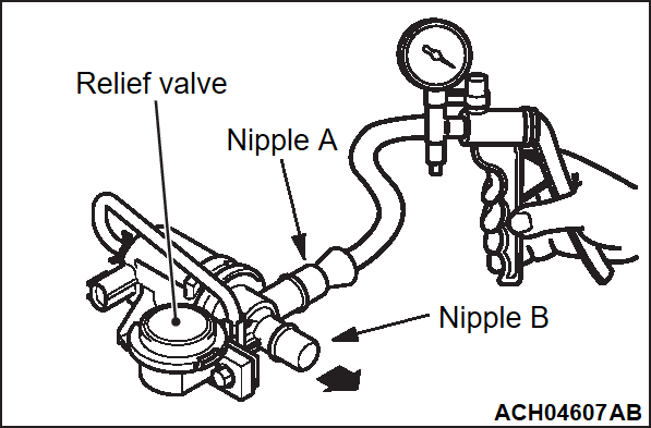
4. Connect a hand vacuum pump (pressure-application type) to nipple (A) of the fuel tank solenoid valve (refer to the illustration).
5. Apply pressure to nipple A of the fuel tank solenoid valve, and check that air leaks from nipple B when it is at approximately 33 kPa (4.79 psi) or more.
6. When air does not leak at approximately 33 kPa (4.79 psi) or more, it is considered that the relief valve attached to the fuel tank solenoid valve is abnormal, so replace the fuel tank solenoid valve.
7. Install the floor inspection lid (RH) (Refer to Body Exterior Doors, Roof & Vehicle Security - Exterior, Loose Panel Removal and Installation REMOVAL AND INSTALLATION )
)
 )
)8. Install the second seat assembly (Refer to Body Interior - Seat, Removal and Installation, Second Seat Assembly, Removal and Installation Removal and Installation ).
).
 ).
).![[Previous]](../../../buttons/fprev.png)
![[Next]](../../../buttons/fnext.png)


