DTC P0134-00: Linear A/F sensor circuit no activity detected
CIRCUIT OPERATION
The linear air-fuel ratio sensor and the ECM are connected by the following three lines to detect the air-fuel ratio.
- The line between the linear air-fuel ratio sensor terminal number 6 and the ECM connector terminal number 54 detects the air-fuel ratio.
- The auxiliary line between the linear air-fuel ratio sensor connector terminal number 1 and the ECM connector terminal number 53 detects the air-fuel ratio.
- The line between the linear air-fuel ratio sensor connector terminal number 5 and the ECM connector terminal number 51 is connected to ground.
TECHNICAL DESCRIPTION
- The ECM effects air/fuel ratio feedback control in accordance with the signals from the linear air-fuel ratio sensor.
- If the linear air-fuel ratio sensor has deteriorated, corrections will be made by the heated oxygen sensor (rear).
DESCRIPTIONS OF MONITOR METHODS
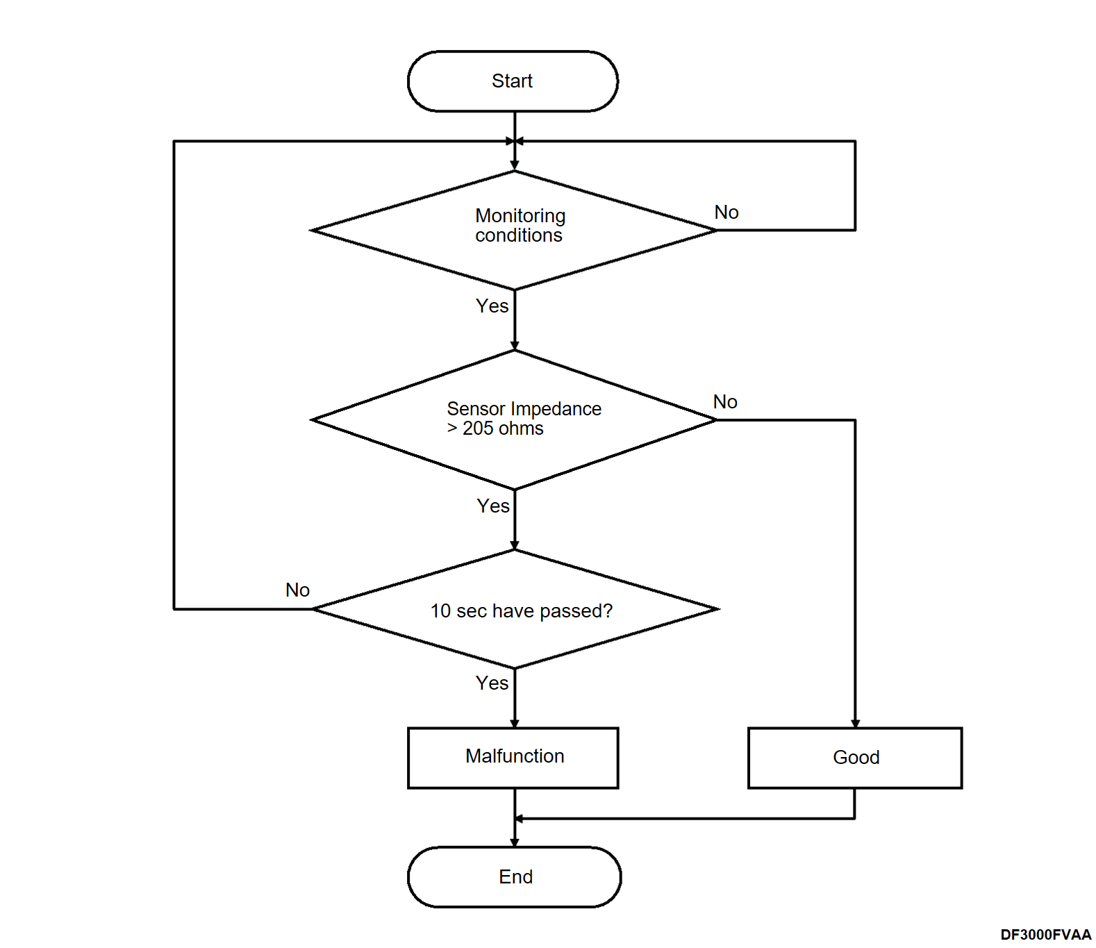
The linear air-fuel ratio sensor is heated by the linear air-fuel ratio sensor heater or the exhaust gas. If the linear air-fuel ratio sensor remains not activated although being under the conditions where it can sufficiently be activated, the DTC is set as a malfunction.
MONITOR EXECUTION
Continuous.
MONITOR EXECUTION CONDITIONS (Other monitor and Sensor)
Other Monitor (There is no temporary DTC set in memory for the item monitored below)
- Linear air-fuel ratio sensor heater monitor
- Misfire monitor
- Fuel system monitor
Sensor (The sensor below is determined to be normal)
- Mass airflow sensor
- Engine coolant temperature sensor
- Intake air temperature sensor
- Barometric pressure sensor
- Throttle position sensor
- Fuel tank pressure sensor
Check Conditions
- 12V battery positive voltage is between 10.0 and 16.5 volts.
- More than 180 seconds have passed since the engine starting sequence was completed.
Judgment Criterion
- The sensor impedance is be higher than 205 ohms for 10 seconds.
FAIL-SAFE AND BACKUP FUNCTION
Does not control air-fuel ratio closed loop.
OBD-II DRIVE CYCLE PATTERN
Refer to Diagnostic Function, OBD-II Drive Cycle – Pattern 2 OBD- II DRIVE CYCLE .
.
 .
.TROUBLESHOOTING HINTS (The most likely causes for this code to be set are:)
- Linear air-fuel ratio sensor failed.
- Open linear air-fuel ratio sensor circuit, harness damage or connector damage.
DIAGNOSIS
Required Special Tools:
- MB992744: Vehicle communication interface-Lite (V.C.I.-Lite)
- MB992745: V.C.I.-Lite main harness A
- MB992747: V.C.I.-Lite USB cable short
- MB992748: V.C.I.-Lite USB cable long
1.STEP 1. Check harness between linear air-fuel ratio sensor connector terminal number 1 and ECM connector terminal number 53.
Check output line for open circuit and damage. Repair or replace the connector, or repair the damaged harness wire.
Q: Is the check result normal?
 Repair or replace the connector, or repair the damaged harness wire.
2.STEP 2. Check harness between linear air-fuel ratio sensor connector terminal number 5 and ECM connector terminal number 51.
Check ground line for open circuit and damage. Repair or replace the connector, or repair the damaged harness wire.
Q: Is the check result normal?
 Repair or replace the connector, or repair the damaged harness wire.
3.STEP 3. Test the OBD-II drive cycle after replace the linear air-fuel ratio sensor.
After erasing the DTC, carry out test drive with the drive cycle pattern, and recheck the DTC. Replace the linear air-fuel ratio sensor (Refer to ENGINE, Engine, Motor and Emission Control – Emission Control – Exhaust Gas Purification System CATALYTIC CONVERTER REMOVAL AND INSTALLATION
 ).
). Intermittent malfunction (Refer to GENERAL INFORMATION, General Information – How to Use Troubleshooting/Inspection Service Points HOW TO COPE WITH INTERMITTENT MALFUNCTIONS
 ).
).
(1) Use scan tool (M.U.T.-III SE) to erase the DTC.
(2) Carry out test drive with the drive cycle pattern (Refer to Diagnostic Function, OBD-II Drive Cycle – Pattern 2 OBD- II DRIVE CYCLE ).
).
 ).
).(3) Use scan tool (M.U.T.-III SE) to recheck the DTC.
Q: Is DTC P0134-00 set?
 Replace the linear air-fuel ratio sensor (Refer to ENGINE, Engine, Motor and Emission Control – Emission Control – Exhaust Gas Purification System CATALYTIC CONVERTER REMOVAL AND INSTALLATION
 ).
). Intermittent malfunction (Refer to GENERAL INFORMATION, General Information – How to Use Troubleshooting/Inspection Service Points HOW TO COPE WITH INTERMITTENT MALFUNCTIONS
 ).
).![[Previous]](../../../buttons/fprev.png)
![[Next]](../../../buttons/fnext.png)
