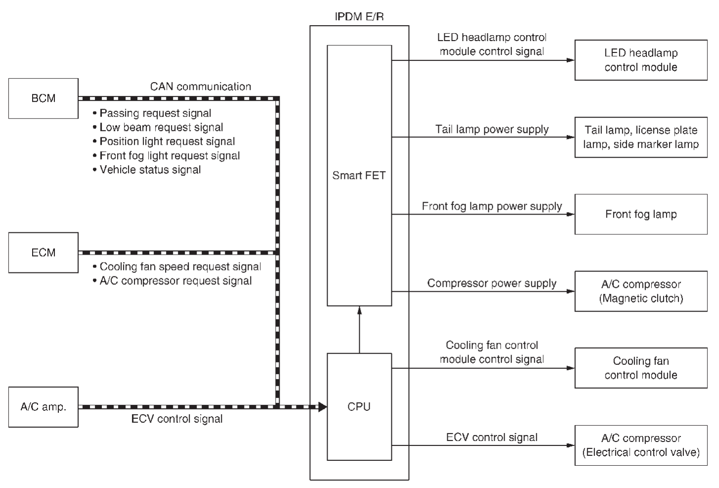
| BCM | BCM transmits the each light ON/OFF request signal and vehicle status signal to IPDM E/R via CAN communication. |
| ECM | - ECM calculates a cooling level, and transmits cooling fan speed request signal to IPDM E/R via CAN communication.
- ECM transmits A/C compressor request signal to IPDM E/R via CAN communication according to status of the engine and refrigerant pressure.
|
| A/C amp. | A/C amp. transmits the ECV control signal to IPDM E/R via CAN communication. |
| IPDM E/R | - IPDM E/R controls the smart FET to control each light according to the control signal status of each light received from BCM via CAN communication. Refer to the following.
- IPDM E/R controls the smart FET to control A/C compressor (magnetic clutch) according to the A/C compressor request signal received from ECM via CAN communication. Refer to A/C Compressor Control
 (automatic air conditioning) or A/C Compressor Control (automatic air conditioning) or A/C Compressor Control (manual air conditioning). (manual air conditioning). - IPDM E/R controls the cooling fan control module according to the cooling fan speed request signal received from ECM via CAN communication. Refer to System Description
 . . - IPDM E/R controls the A/C compressor (electrical control valve) according to the ECV control signal received from A/C amp. via CAN communication. Refer to A/C Compressor Control
 (automatic air conditioning) or A/C Compressor Control (automatic air conditioning) or A/C Compressor Control (manual air conditioning). (manual air conditioning).
|
| Smart FET | Refer to Smart FET . . |
| LED headlight control module | IPDM E/R supplies power supply voltage to each light, and turns the each light ON. |
| Tail light, license plate light, side marker light |
| Front fog light |
| A/C compressor (Magnetic clutch) | IPDM E/R supplies power supply voltage to A/C compressor (magnetic clutch), and turns the magnetic clutch ON. |
| Cooling fan control module | IPDM E/R controls the each actuators. |
| A/C compressor (Electrical control valve) |
 .
.![[Previous]](../../../buttons/fprev.png)
![[Next]](../../../buttons/fnext.png)
