System Description
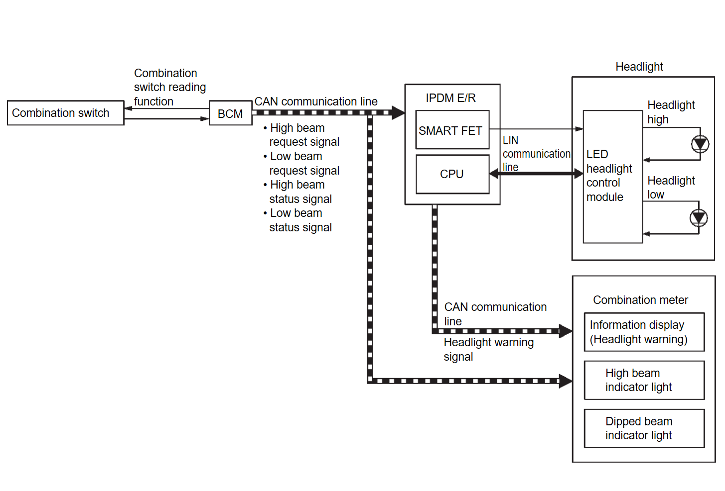
SYSTEM DIAGRAM
| Component | Function | |
| Headlight | Headlight (HI) (LED headlight) |
|
| Headlight (LO) (LED headlight) |
| |
| LED headlight control module | Refer to LED Headlight Control ModuleLED Headlamp Control Module . . | |
| IPDM E/R |
| |
| BCM |
| |
| Combination meter |
| |
| Combination switch | Lighting & turn signal switch | Inputs the each switch condition signal to BCM. |
OUTLINE
Headlight is controlled by combination switch reading function and headlight control function of BCM, and smart FET control function and LIN communication function of IPDM E/R.
HEADLIGHT (LO) OPERATION
- BCM detects the combination switch condition with the combination switch reading function.
- BCM transmits the low beam request signal to IPDM E/R and low beam status signal to the combination meter via CAN communication according to the headlight (LO) ON condition.Headlight (LO) ON condition (When any of the following conditions are satisfied)
- Lighting switch 1ST (Only when the illumination judgement by auto light function is ON. Refer to System Description
 .) (For Canada)
 - Lighting switch 2ND
- Lighting switch AUTO (Only when the illumination judgement by auto light function is ON. Refer to System Description
 .)
.) - Lighting switch PASS
- Lighting switch 1ST (Only when the illumination judgement by auto light function is ON. Refer to System Description
- IPDM E/R turns the integrated smart FET ON according to low beam request signal, and transmits the control signal to LED headlight control module.
- IPDM E/R transmits the request to LED headlight control module (via LIN communication) according to low beam request signal.
- LED headlight control module turns the headlight (LO) ON according to the control signal and request (via LIN communication) from IPDM E/R.
- Combination meter turns the dipped beam indicator light according to the low beam status signal. (Full TFT meter models)
HEADLIGHT (HI) OPERATION
- BCM transmits the high beam request signal to IPDM E/R and high beam status signal to the combination meter via CAN communication according to the headlight (HI) ON condition. Headlight (HI) ON condition (When any of the following conditions are satisfied)For Canada
- Lighting switch HI with the lighting switch 1ST or AUTO (Only when the illumination judgement by auto light function is ON. Refer to System Description
 .)
.) - Lighting switch HI with the lighting switch 2ND
- High beam assist switch ON with the lighting switch 1ST or AUTO (Only when the illumination judgement by auto light function is ON and the illumination judgement by high beam assist system is ON. Refer to System Description
 .)
.) - Lighting switch PASS
Except for Canada- Lighting switch HI with the lighting switch 2ND
- Lighting switch HI with the lighting switch AUTO (Only when the illumination judgement by auto light function is ON. Refer to System Description
 .)
.) - High beam assist switch ON with the lighting switch AUTO (Only when the illumination judgement by auto light function is ON and the illumination judgement by high beam assist system is ON. Refer to System Description
 .)
.) - Lighting switch PASS
- Lighting switch HI with the lighting switch 1ST or AUTO (Only when the illumination judgement by auto light function is ON. Refer to System Description
- IPDM E/R turns the integrated smart FET ON according to high beam request signal, and transmits the control signal to LED headlight control module.
- IPDM E/R transmits the request to LED headlight control module (via LIN communication) according to high beam request signal.
- LED headlight control module turns the headlight (HI) ON according to the control signal and request (via LIN communication) from IPDM E/R.
- Combination meter turns the high beam indicator light ON according to the high beam status signal.
HEADLIGHT WARNING OPERATION
Headlight warning warns the driver that there is a malfunction in LED headlight system. Refer to Headlight WarningHeadlamp Warning .
.
 .
.LED HEADLIGHT
- Semiconductor device (Light emitting diode: LED), which is illuminated when forward bias electric voltage is applied, is adopted as the source of light instead of halogen bulb or xenon bulb.
- Comparing to halogen headlight or xenon headlight, LED headlight is electrically power saving, durable, and is illuminated in the similar color to the sunlight. Bright, natural, and eye-friendly visibility can be obtained.
Precautions for Trouble Diagnosis
Representative malfunction examples are; “Light does not turn ON”, “Light blinks”, and “Brightness is inadequate.” Such malfunctions, however, occasionally by occur LED control module malfunction or light case malfunction. Specify the malfunctioning part with diagnosis procedure.
| caution |
|
| note | Turn the switch OFF once before turning ON, if the ON/OFF is inoperative. |
![[Previous]](../../../buttons/fprev.png)
![[Next]](../../../buttons/fnext.png)
