System Description
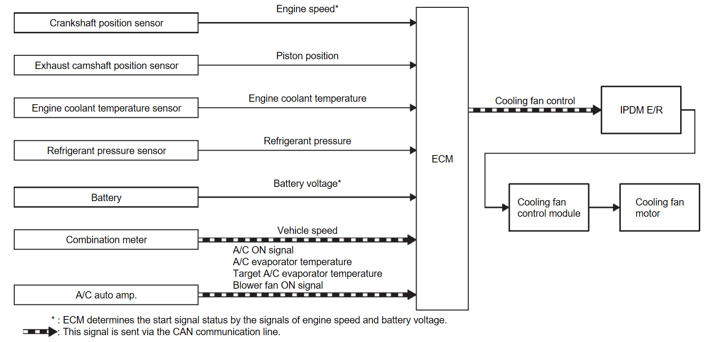
System Diagram
| Component parts | Function |
| Crankshaft position sensor | Crankshaft Position Sensor |
| Exhaust camshaft position sensor | Exhaust Camshaft Position Sensor |
| Engine coolant temperature sensor | Engine Coolant Temperature Sensor |
| Refrigerant pressure sensor | Refrigerant Pressure Sensor |
| Battery | ECM receives the battery voltage signal. |
| A/C auto amp. | ECM receives below signal via CAN communication
|
| Combination meter | ECM receives the vehicle speed signal via CAN communication. |
| IPDM E/R | ECM transmits the A/C relay control signal via CAN communication. |
| Cooling fan relay | Cooling Fan |
| Cooling fan motor |
SYSTEM DESCRIPTION
Cooling fan control signal is sent to IPDM E/R from ECM by CAN communication line. Then, IPDM E/R sends ON/OFF pulse duty signal to cooling fan control module. Corresponding to this ON/OFF pulse duty signal, cooling fan control module gives cooling fan motor operating voltage to cooling fan motors. Cooling fan speed is controlled by duty cycle of cooling fan motor operating voltage sent from cooling fan control module.
Cooling Fan Speed Request for Cooling the Engine
Cooling fan speed for cooling the engine is judged based on vehicle speed, engine coolant temperature, air conditioner ON signal, refrigerant pressure, target A/C evaporator temperature, and A/C evaporator temperature.
![[Previous]](../../../buttons/fprev.png)
![[Next]](../../../buttons/fnext.png)
