DTC Diagnosis Procedure
1.CHECK EXHAUST GAS LEAK
- Start engine and run it at idle.
- Listen for an exhaust gas leak before three way catalyst (manifold).
Is exhaust gas leak detected?
 Repair or replace error-detected parts.
2.CHECK FOR INTAKE AIR LEAK
- Listen for an intake air leak after the mass air flow sensor.
- Check PCV hose connection.
Intake air leak detected?
 Repair or replace error-detected parts.
3.CHECK A/F SENSOR 1 INPUT SIGNAL CIRCUIT
- Turn ignition switch OFF.
- Disconnect corresponding A/F sensor 1 harness connector.
- Disconnect ECM harness connector.
- Check the continuity between A/F sensor 1 harness connector and ECM harness connector.
+ − Continuity A/F sensor 1 ECM Connector Terminal Connector Terminal F18 1 F51 56 Existed 2 60 - Check the continuity between A/F sensor 1 harness connector and ground, or ECM harness connector and ground.
+ − Continuity A/F sensor 1 Connector Terminal F18 1 Ground Not existed 2 + − Continuity ECM Connector Terminal F51 56 Ground Not existed 60 - Also check harness for short to power.
Is the inspection result normal?
 Repair or replace error-detected parts.
4.CHECK FUEL PRESSURE
5. DETECT MALFUNCTIONING PART
Check fuel hoses and fuel tubes for clogging. Refer to Exploded View .
. Replace “fuel filter and fuel pump assembly”. Refer to Exploded View
 .
. Repair or replace error-detected parts.
 .
.Is the inspection result normal?
 Replace “fuel filter and fuel pump assembly”. Refer to Exploded View
 .
. Repair or replace error-detected parts.
6.CHECK MASS AIR FLOW SENSOR
 With M.U.T.-III SE
- Install all removed parts.
- Check “MASS AIR FLOW SENSOR (g/s)” in “DATA MONITOR” mode of “ENGINE” using M.U.T.-III SE.
- For specification, refer to Component Inspection
 .
.
 With GST
- Install all removed parts.
- Check mass air flow sensor signal in Service $01 with GST.
- For specification, refer to MASS AIR FLOW SENSOR : Service Data
 .
.
Is the measurement value within the specification?
 Check connectors for rusted terminals or loose connections in the mass air flow sensor circuit or grounds. Refer to DTC Description
 .
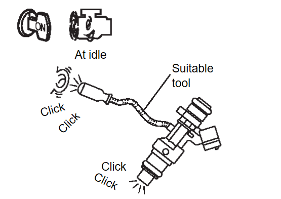
.7.CHECK FUNCTION OF FUEL INJECTOR
 With M.U.T.-III SE
- Start engine.
- Perform "POWER BALANCE" in "Actuator Test" (in "Special Function") mode of "ENGINE" using M.U.T.-III SE.
- Make sure that each circuit produces a momentary engine speed drop.
Is the inspection result normal?
 INSPECTION END
 Perform trouble diagnosis for “FUEL INJECTOR”, refer to Component Function Check
 .
.![[Previous]](../../../buttons/fprev.png)
![[Next]](../../../buttons/fnext.png)

 Without M.U.T.-III SE