DTC Diagnosis Procedure
1.CHECK DTC PRIORITY
If DTC P0335 is displayed with DTC P06B0, first perform the trouble diagnosis for DTC P06B0. Perform diagnosis of applicable. Refer to DTC Description
 .
.
Is applicable DTC detected?
 Perform diagnosis of applicable. Refer to DTC Description
 .
.2.CHECK HARNESS CONNECTOR
- Turn ignition switch OFF.
- Disconnect crankshaft position (CKP) sensor harness connectors.
- Reconnect crankshaft position (CKP) sensor harness connectors.
- Perform DTC confirmation procedure.
Is DTC detected?
 INSPECTION END
3.CHECK GROUND CONNECTION
4.CHECK CRANKSHAFT POSITION (CKP) SENSOR POWER SUPPLY
- Turn ignition switch OFF.
- Disconnect crankshaft position (CKP) sensor (POS) harness connector.
- Turn ignition switch ON.
- Check the voltage between CKP sensor (POS) harness connector and ground.
CKP sensor (POS) Condition Voltage (Approx.)Connector + − Terminal F17 1 2 Ignition switch: ON 5 V Ignition switch: OFF 0 V
Is the inspection result normal?
5.CHECK CKP SENSOR (POS) POWER SUPPLY CIRCUIT-2
- Turn ignition switch OFF.
- Disconnect ECM harness connector.
- Check the continuity between CKP sensor (POS) harness connector and ECM harness connector.
| CKP sensor (POS) | ECM | Continuity | ||
| Connector | Terminal | Connector | Terminal | |
| F17 | 1 | F52 | 78 | Existed |
Is the inspection result normal?
 Repair or replace malfunctioning part.
6.CHECK CKP SENSOR GROUND CIRCUIT
- Turn ignition switch OFF.
- Disconnect ECM harness connector.
- Check the continuity between CKP sensor harness connector and ECM harness connector.
+ − Continuity CKP sensor ECM Connector Terminal Connector Terminal F17 2 F52 108 Existed
Is the inspection result normal?
 Repair or replace error-detected parts.
7.CHECK ECM GROUND CIRCUIT
- Check the continuity between ECM harness connector and ground.
ECM — Continuity Connector Terminal F51 4 Ground Existed E16 156 157 160 - Also check harness for short to power.
Is the inspection result normal?
 Repair or replace malfunctioning part.
8.CHECK CKP SENSOR (POS) POWER SUPPLY CIRCUIT-3
- Check the continuity between CKP sensor harness connector and ECM harness connector.
+ − Continuity CKP sensor ECM Connector Terminal Connector Terminal F17 3 F52 96 Existed - Also check harness for short to ground and to power.
Is the inspection result normal?
 Repair or replace error-detected parts.
9.CHECK CKP SENSOR (POS)
Check the crankshaft position sensor. Refer to Component InspectionComponent Inspection (Crankshaft Position sensor) .
. Replace crankshaft position sensor (POS). Refer to Exploded View
 .
.
 .
.Is the inspection result normal?
 Replace crankshaft position sensor (POS). Refer to Exploded View
 .
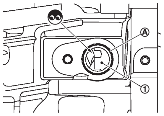
.10.CHECK GEAR TOOTH
- Remove crankshaft position sensor. Refer to Exploded View
 .
. - Look into the mounting hole
 of the crankshaft position sensor to check that there is no missing gear tooth in the signal plate
 .
.
Is the inspection result normal?
 INSPECTION END
 Replace the signal plate. Refer to Exploded View
 .
.![[Previous]](../../../buttons/fprev.png)
![[Next]](../../../buttons/fnext.png)
