Removal and Installation
REMOVAL
2WD models
1. Remove the engine cover.(With engine cover models) Refer to Removal and Installation.Removal and Installation

2. Disconnect the air fuel ratio sensor 1 harness connector.
3. Remove the air fuel ratio sensor 1 using heated oxygen sensor wrench [SST: KV10117100] if necessary.
4. Remove the engine under cover. Refer to Removal and Installation .
.
 .
.5. Remove the exhaust front tube. Refer to Removal and Installation .
.
 .
.6. Remove the exhaust manifold and three way catalyst bracket.
7. Remove the EGR inlet tube heat insulator. Refer to Removal and Installation .
.
 .
.8. Remove the EGR inlet tube mounting bolt, exhaust manifold and three way catalyst side. Refer to Removal and Installation .
.
 .
.9. Remove the exhaust manifold and three way catalyst cover.
11. Remove the exhaust manifold and three way catalyst assembly and gasket.
AWD models
1. Remove the engine cover (with engine cover models). Refer to Removal and Installation.Removal and Installation

2. Disconnect the exhaust gas temperature harness connector.
3. Remove the exhaust gas temperature sensor.
4. Disconnect the air fuel ratio sensor 1 harness connector.
5. Remove the air fuel ratio sensor 1 using heated oxygen sensor wrench [SST: KV10117100] if necessary.
6. Remove the engine under cover. Refer to Removal and Installation .
.
 .
.7. Remove the exhaust front tube. Refer to Removal and Installation .
.
 .
.8. Remove rear propeller shaft. Refer to Removal and Installation .
.
 .
.9. Remove the exhaust manifold and three way catalyst bracket.
10. Remove the EGR inlet tube heat insulator. Refer to Removal and Installation .
.
 .
.11. Remove the EGR inlet tube mounting bolt, exhaust manifold and three way catalyst side. Refer to Removal and Installation .
.
 .
.12. Remove the exhaust manifold and three way catalyst cover.
14. Remove the exhaust manifold and three way catalyst assembly and gasket.
INSTALLATION
Exhaust Manifold and Three Way Catalyst
1. Install studs in cylinder head and exhaust manifold and three way catalyst if removed. Then tighten to specification.
| caution | Do not reuse stud bolts. |
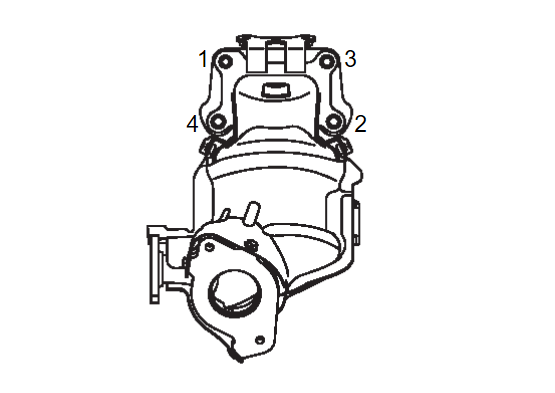
2. Install the exhaust manifold and three way catalyst and gasket. Then tighten the nuts to specification in the numerical order shown.
 | : 41.65 N·m (4.2 kg-m, 31 ft-lb) |
| caution |
|
3. Then tighten the nuts to specification in the numerical order shown again.
 | : 41.65 N·m (4.2 kg-m, 31 ft-lb) |
4. Install exhaust manifold and three way catalyst cover and bolts.
| caution | Do not reuse bolts. |
5. Install the air fuel ratio sensor 1 using heated oxygen sensor wrench [SST: KV10117100] if removed and tighten to specification.
| caution |
|
6. Install the exhaust gas temperature sensor to the specified torque.
| caution |
|
![[Previous]](../../../buttons/fprev.png)
![[Next]](../../../buttons/fnext.png)
