Removal and Installation
REMOVAL
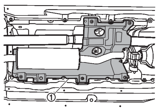
1. Remove engine under cover. Refer to Exploded View .
.
 .
.2. Disconnect fixed parts between main muffler and exhaust front tube. Refer to Removal and Installation .
.
 .
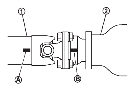
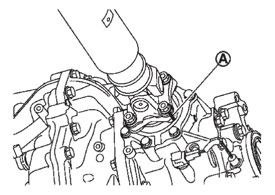
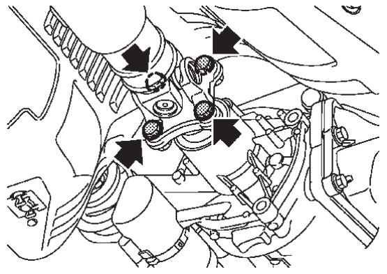
.4. Put matching marks  on propeller shaft flange yoke and transfer companion flange.
 on propeller shaft flange yoke and transfer companion flange.
| caution | For matching mark, use paint. Never damage propeller shaft flange yoke and transfer companion flange. |
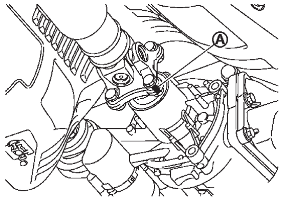
5. Put matching marks  on propeller shaft flange yoke and rear final drive companion flange.
 on propeller shaft flange yoke and rear final drive companion flange.
| caution | For matching mark, use paint. Never damage propeller shaft flange yoke and rear final drive companion flange. |
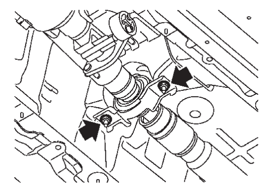
6. Loosen mounting nuts of center bearing mounting bracket.
| note | Tighten mounting nuts temporarily to prevent drop of propeller shaft. |
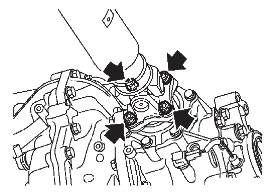
7. Remove propeller shaft assembly fixing bolts, and separate propeller shaft assembly from transfer companion flange.
8. Remove propeller shaft assembly fixing bolts and nuts, and separate propeller shaft assembly from rear final drive companion flange.
9. Remove center bearing mounting bracket mounting nuts.
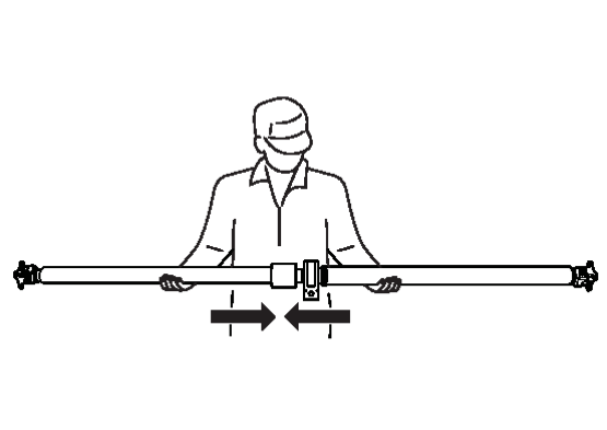
10. Remove propeller shaft assembly.
| caution |
|
11. Perform inspection after removal. Refer to Inspection .
.
 .
.INSTALLATION
Note the following, and install in the reverse order of removal.
- For non-reusable parts, refer to Exploded View
 .
. - For each tightening torque, refer to Exploded View
 .
. - Remove any moisture, oil, or foreign material from matching surface on transfer companion flange, rear final drive companion flange and propeller shaft flange.
- Align matching marks
 to install propeller shaft flange yoke and rear final drive companion flange.
 - Align matching marks
 to install propeller shaft flange yoke and transfer companion flange.
 - If propeller shaft assembly or final drive assembly has been replaced, connect them as follows:
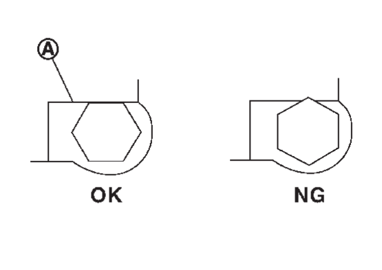
- The bolt head should not become out of alignment due to interference between the bolt hexagonal head and the stopper
 .
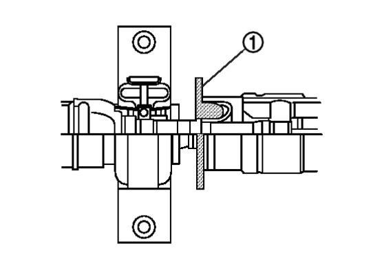
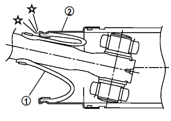
. - Protector
 on boot interference area must be removed after installing propeller shaft assembly.
 - Perform inspection after installation. Refer to Inspection
 .
.
![[Previous]](../../../buttons/fprev.png)
![[Next]](../../../buttons/fnext.png)
 with shop cloth or rubber to protect boot from breakage.
 of final drive