Removal and Installation
REMOVAL
EGR VOLUME CONTROL VALVE
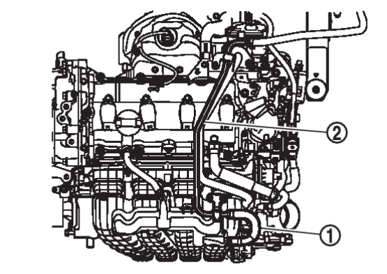
1. Remove engine cover (with engine cover models). Refer to Removal and Installation .
.
 .
.4. Disconnect EGR volume control valve harness connector.
5. Remove the EGR volume control valve.
| caution |
|
6. Remove the stud bolt from EGR cooler bracket if necessary.
EGR COOLER
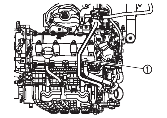
1. Remove the EGR volume control valve.
| caution | Handle carefully to avoid any damage to the EGR system. |
2. Drain engine coolant. Refer to Draining

3. Disconnect brake fluid level switch harness connector. Refer to Removal and Installation .
.
 .
.4. Remove battery tray. Refer to Removal and Installation.Removal and Installation

5. Remove the exhaust manifold and three way catalyst. Refer to Removal and Installation.Removal and Installation

6. Remove the EGR inlet tube heat insulator.
| caution | Do not reuse bolts. |
7. Remove the EGR inlet tube.
| caution | Do not reuse EGR inlet tube gasket. |
8. Remove EGR cooler with EGR cooler bracket.
| caution | Do not reuse EGR cooler gasket. |
9. Separate EGR cooler bracket from EGR cooler if necessary.
INSTALLATION
- Note the following and install in the reverse order of removal
- If replacing EGR volume control valve, perform "EGR volume control valve closed position learning". Refer to Description
 .
.
EGR COOLER AND EGR VOLUME CONTROL VALVE
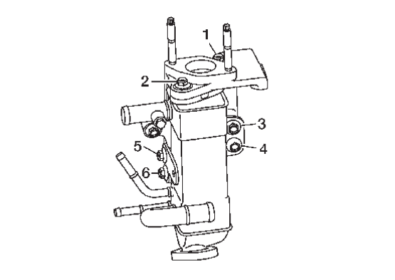
1. Install the EGR cooler to EGR cooler bracket if separate and tighten the bolts to the specified torque in the sequence shown.
| caution | Do not reuse EGR cooler gasket. |
 | : 25.0 N·m (2.6 kg-m, 18 ft-lb) |
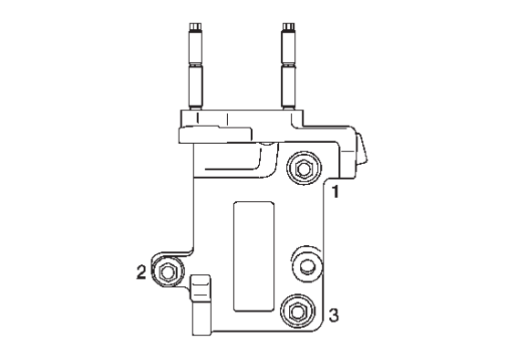
2. Install the EGR cooler bracket with EGR cooler and tighten the bolts to the specified torque in the sequence shown.
 | : 25.0 N·m (2.6 kg-m, 18 ft-lb) |
| caution | Do not reuse EGR cooler gasket. |
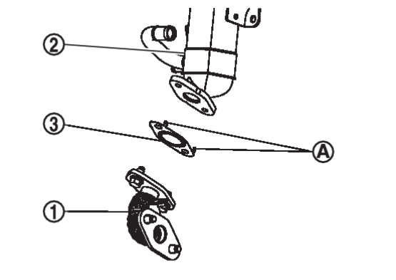
3. Install the EGR inlet tube  to EGR cooler
  , EGR inlet tube bolt temporary tightening.
 to EGR cooler
  , EGR inlet tube bolt temporary tightening.
| caution | Install EGR inlet tube gasket  to set pawls to set pawls  EGR cooler side. EGR cooler side. |
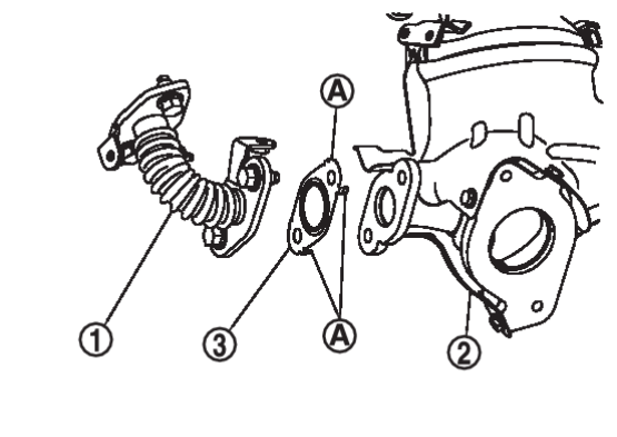
4. Install the EGR inlet tube  to exhaust manifold and three way catalyst assembly
  , EGR inlet tube bolt temporary tightening.
 to exhaust manifold and three way catalyst assembly
  , EGR inlet tube bolt temporary tightening.
| caution | Install EGR inlet tube gasket  to set pawls to set pawls  exhaust manifold and three way catalyst assembly side. exhaust manifold and three way catalyst assembly side. |
5. Install the EGR inlet tube to EGR cooler , EGR inlet tube bolt specified torque tightening.
 | : 25.0 N·m (2.6 kg-m, 18 ft-lb) |
6. Install the EGR inlet tube to exhaust manifold and three way catalyst assembly , EGR inlet tube bolt specified torque tightening.
 | : 50.0 N·m (5.1 kg-m, 37ft-lb) |
7. Install the EGR inlet tube heat insulator, EGR inlet tube heat insulator bolt temporary tightening.
8. Install the EGR inlet tube heat insulator, EGR inlet tube heat insulator bolt specified torque tightening.
| caution | Do not reuse EGR inlet tube heat insulator bolt. |
 | : 5.8 N·m (0.59 kg-m, 51in-lb) |
9. Install the EGR outlet tube to EGR volume control valve, EGR outlet tube nuts temporary tightening.
| caution | Do not reuse EGR volume control valve gasket. |
10. Install the EGR outlet tube to intake manifold, EGR outlet tube bolt specified tightening.
 | : 25.0 N·m (2.6 kg-m, 18 ft-lb) |
11. Install the EGR outlet tube to EGR volume control valve, EGR outlet tube nuts specified tightening.
 | : 25.0 N·m (2.6 kg-m, 18 ft-lb) |
12. Installation of the remaining components is in the reverse order of removal.
![[Previous]](../../../buttons/fprev.png)
![[Next]](../../../buttons/fnext.png)
